Blog
How to Read Control Wiring Diagrams
The schematic that shows a panel's logic looks like hieroglyphics until you learn its grammar: two supply rails, one decision per rung, NO/NC contacts, device codes and the start-stop seal-in circuit that gives a machine its memory.
 Tan Kok XinBuilding Electrical Fundamentals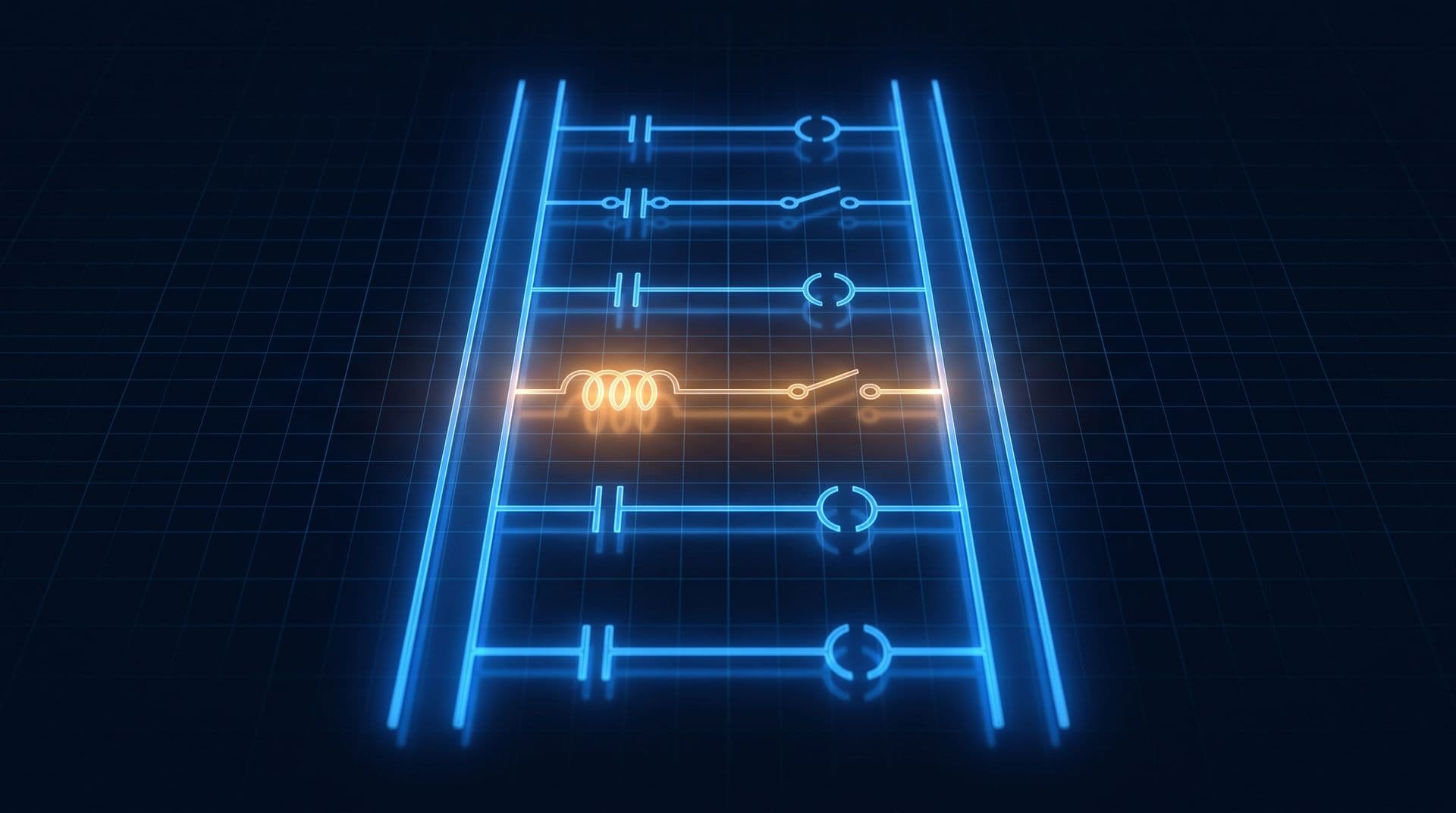
Part 10 of 11 in Cobler's Building Electrical Fundamentals course. New here? See the course page.
Part 9 opened a pump starter panel and ended with the numbered wires that link each part to the panel's drawings. How do you read a control wiring diagram?
At two in the morning, the building management system (BMS) in the office tower shows that chilled-water pump CHWP-2 will not start. The chargeman on call does not start by opening the panel. They take the panel's folder of drawings, find the page for the pump's control circuit and follow one line across it with a finger. A few minutes later they know which part to check.
A control wiring diagram looks confusing at first, but it follows a small number of rules. This part teaches those rules one at a time, using the control circuit of the same pump panel from Part 9. It ends with a short exercise you can do on paper. As in every part of this course, reading drawings is something anyone can learn; opening panels and testing circuits is work for the competent person.
What is a control wiring diagram?
A control wiring diagram shows the logic of a panel's control circuit: under what conditions each part switches on.
It answers a different question from the single line diagram (Part 3). The single line diagram shows where power flows through the building, from the transformer to the switchboards and out to the equipment. A control wiring diagram shows how one panel decides, for example when a pump should start and what stops it.
Most control wiring diagrams are drawn like a ladder:
- Two long lines, called rails, carry the control supply. In the tower's 230 V AC pump panels, one rail is the live side (L) and the other is the neutral (N). In a 24 V DC panel, they are +24 V and 0 V.
- Between the rails run shorter lines, called rungs. Each rung is one circuit: a path that current can take from one rail to the other.
In this lesson, the rails run down the sides of the page and the rungs run across. Many drawings made to IEC (International Electrotechnical Commission) standards turn this on its side, with the supply lines across the top and bottom and each circuit running down the page. You read those in the same way: from one supply line to the other.
How to read a single rung
Read each rung from the live rail to the return rail. Current can reach the end of the rung only if every condition along the way allows it.
The conditions are contacts: small switches that are either open (no current passes) or closed (current passes). The result, drawn just before the return rail, is usually a coil, drawn as a circle, or a lamp. When there is a closed path through the contacts, current reaches the coil and energises it. If the path is broken anywhere, the coil stays off.
Contacts can be arranged in two ways:
- In series, one after another along the same line. All of them must be closed. You can read this as "this AND this".
- In parallel, on separate branches side by side. Any one of them being closed is enough. You can read this as "this OR this".
So each rung reads like a sentence: "IF these conditions are met, THEN energise this coil." The order of contacts in series does not change the result: if any one is open, the path is broken.
Normally open and normally closed contacts
A contact is drawn in one of two ways, and they mean opposite things.
- A normally open (NO) contact is drawn as two short bars with a gap between them. When its device is at rest, the contact is open and blocks current. It closes when its device operates.
- A normally closed (NC) contact is drawn as the same two bars with a diagonal line across them. When its device is at rest, the contact is closed and lets current through. It opens when its device operates.
The word "normally" does not mean "usually" or "during normal running". It means the resting state: the position the contact is in when nobody is pressing the button, the coil is not energised and the device has not tripped. Every contact on the drawing is shown in that resting state.
A Stop button is drawn normally closed. At rest it lets current through, and pressing it opens the circuit. This choice is deliberate: if a wire to the Stop button breaks, the circuit opens and the pump stops, which is the safe result. A Start button is drawn normally open. At rest it blocks current, and pressing it closes the circuit.
(The two-bar symbols used in this lesson are common in ladder diagrams. IEC drawings show a contact as a small switch blade, drawn open or closed. The meaning is the same.)
What the letters and numbers mean
Every device on the drawing has a label made of letters and a number. The letters say what kind of device it is, and the number says which one.
Different drawings use different letter conventions. In this course we use IEC 81346-2, the current international standard for these letter codes (it replaced the older IEC 61346). It uses two letters: the first gives the main job, and the second narrows it down.
Letters | What the device does | Examples |
|---|---|---|
QA, QB | Switches or isolates a power circuit | QA: contactor, circuit breaker. QB: isolator |
KF | Processes control signals | Control relay, timer relay, BMS interface relay |
FC | Protects against overcurrent | Overload relay, fuse |
SF | Turns a hand action into a signal | Push-button, selector switch |
PF | Shows a state | Indicator lamp |
MA | Drives something with a motor | Pump motor |
Devices are numbered within their letters, so KF1 and KF2 are two different relays. In the tower's pump panel, the contactor is QA1, the overload relay is FC1, the BMS run relay is KF1, the Stop and Start buttons are SF1 and SF2, and the lamps are PF1 and PF2.
Older drawings often use single letters from earlier standards. On those you will see a contactor labelled K1, lamps labelled H and buttons labelled S. Check the legend or title sheet of the drawing set to see which convention it uses.
One device, several places on the page. A contactor has a coil and several contacts, and they can appear on different rungs. All of them carry the same label. So "QA1" next to a coil and "QA1" next to a contact on another rung are parts of the same contactor: when the QA1 coil is energised, every QA1 contact changes state.
Terminal numbers are printed next to each part. They are standard, so they help you recognise the part:
- A1-A2: the two ends of a contactor or relay coil.
- 13-14: a normally open auxiliary contact on a contactor. ("Auxiliary" means a small extra contact for the control circuit, separate from the main power contacts.)
- 21-22: a normally closed auxiliary contact.
- 95-96: the overload relay's normally closed contact, which opens when it trips.
- 97-98: the overload relay's normally open contact, which closes when it trips.
Wire numbers are the last piece. Every wire on the drawing carries a number, and the matching wire in the panel carries a printed sleeve, called a ferrule, with the same number. A competent person who finds wire 5 on a terminal can go straight to wire 5 on the drawing. That is how the chargeman in the opening story found the right place in minutes.
The start-stop circuit keeps itself running
The most common control circuit is the start-stop circuit. It lets a person start a pump with a short press of a button, and the pump keeps running after the button is released.
The rung has four contacts and a coil:
- The Stop button SF1 (normally closed).
- The Start button SF2 (normally open).
- A normally open auxiliary contact of the contactor itself, QA1 13-14, wired in parallel with the Start button.
- The overload contact FC1 95-96 (normally closed).
- At the end, the contactor coil QA1.
Here is what happens, in order:
- At rest, the Start button is open and so is the QA1 13-14 contact. There is no path to the coil, so the contactor is open and the pump is off.
- Press Start. Now there is a complete path, and current reaches the QA1 coil. The contactor closes its main contacts and the pump starts. At the same moment, the contactor's own auxiliary contact QA1 13-14 closes, because it belongs to the same contactor.
- Release Start. The Start button opens again, but current still reaches the coil through the QA1 13-14 contact, which is now closed. The contactor is holding its own coil circuit closed. This is called the seal-in (or holding) contact.
- Press Stop. The Stop button opens and breaks the path. The coil loses its current, the contactor opens and the pump stops. The QA1 13-14 contact opens as well, so when you release Stop, the pump stays off until someone presses Start again.
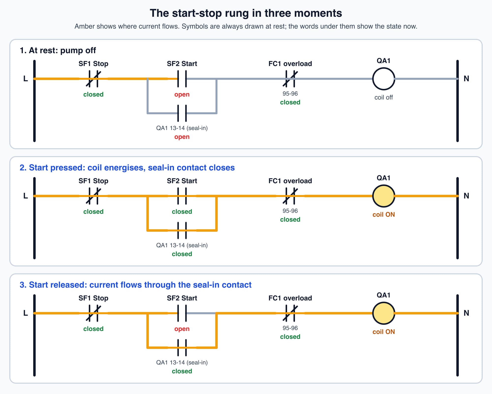
The seal-in contact QA1 13-14 keeps the coil energised after the Start button is released.
The same thing happens if the overload relay trips: FC1 95-96 opens, the coil drops out and the seal-in contact opens. It also happens if the control supply is lost. When the supply comes back, the pump does not restart by itself, because the seal-in contact is open. This is called no-volt protection. It stops machines from starting unexpectedly when power returns.
In a building, some equipment must restart after a power cut, for example after the generator takes over (see When the Mains Fails, Part 8). In that case the BMS or a timer gives a fresh run command, usually in a planned order so that large motors do not all start at once.
Worth knowing: A circuit that switches on with one short signal and stays on until another signal clears it is a simple one-bit memory. The seal-in rung is an early mechanical form of the memory used in digital electronics.
Schematic, wiring diagram or layout: three drawings, three jobs
A panel usually comes with three kinds of drawing, and each answers a different question.
- The schematic, also called the circuit diagram, elementary diagram or ladder diagram, is the kind we have been reading. It shows how the logic works. It is arranged for clarity, so one device's coil and contacts can appear on different rungs. It does not show where parts sit in the panel.
- The connection diagram, also called a wiring diagram, shows which numbered wire lands on which terminal of which device. All of one device's terminals are drawn together. It is used to build the panel and to trace a particular wire.
- The layout or general-arrangement drawing is a scaled picture of the panel door and the mounting plate. It shows where each part is mounted, so you can find it. It shows no logic.
People use "wiring diagram" loosely for all three, so check which one you are holding. A competent person tracing a fault uses them in turn: the schematic to understand why the pump will not start, the connection diagram to find which wire and terminal to check, and the layout to find the part in the panel.
A paper tracing exercise
Here is a simplified control circuit for chilled-water pump CHWP-2 in the office tower. It adds three things to the start-stop rung described earlier:
- A Hand-Off-Auto selector switch, SF3. In Hand, a person starts and stops the pump with the buttons at the panel. In Auto, the BMS runs the pump through its run relay KF1. In Off, neither can start it.
- A RUN lamp, PF1, lit through a second normally open contact of the contactor, QA1 23-24.
- A TRIP lamp, PF2, lit through the overload relay's normally open contact, FC1 97-98.
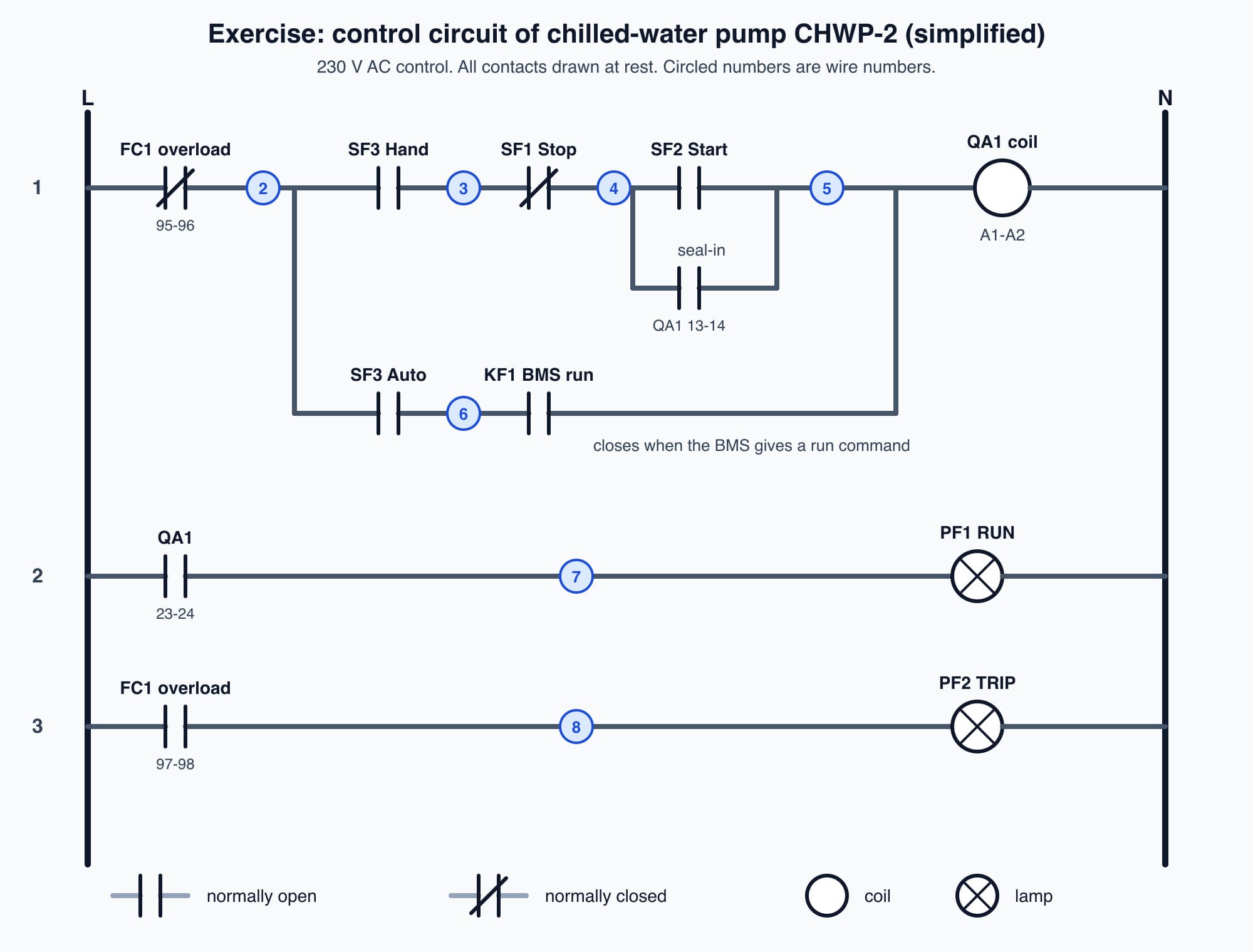
The simplified control circuit of chilled-water pump CHWP-2, with wire numbers; all contacts are drawn at rest.
Try each question on paper before reading the answer.
1. The selector is in Auto and the BMS gives a run command. Which path does current take to the contactor coil? Give the wire numbers.
Answer: From L through the overload contact FC1 95-96 to wire 2, through the SF3 Auto contact to wire 6, through the closed KF1 contact to wire 5, then through the QA1 coil (A1-A2) to N. The Stop and Start buttons are not in this path, so in Auto the BMS starts and stops the pump.
2. The selector is in Hand. Someone presses Start and lets go. Why does the pump keep running, and between which wires is the contact that holds it on?
Answer: While Start is pressed, current flows from wire 4 through SF2 to wire 5 and energises the QA1 coil. The contactor then closes its own auxiliary contact QA1 13-14, which is connected between wire 4 and wire 5, in parallel with the Start button. After Start is released, current keeps flowing through QA1 13-14.
3. The selector is in Off. Can the BMS start the pump?
Answer: No. In Off, both SF3 contacts are open. The path from wire 2 is broken on both branches, so neither the KF1 contact nor the Start button can reach the coil.
4. At 2am the pump is stopped. The TRIP lamp is lit, the RUN lamp is off and the BMS is still giving a run command. What has happened, and why can neither the BMS nor the Start button restart the pump?
Answer: The overload relay FC1 has tripped. Its normally open contact 97-98 has closed, which lights the TRIP lamp through wire 8. At the same time, its normally closed contact 95-96 has opened. That contact sits between L and wire 2, before the path splits into Hand and Auto, so there is no path to the coil in any position. The contactor has opened, so QA1 23-24 is open and the RUN lamp is off. The pump cannot restart until the overload relay is reset, and the reason for the trip should be found first. The next part works through a trip like this one, step by step.
What comes next
A trip lamp tells you which device operated, but not why. The final part, A Trip Is a Clue: Fault Reporting and Electrical Maintenance, follows an overload trip on this same pump, CHWP-2, from the first alarm to the competent person's checks. It starts from the question: when a pump trips, what should you record, who should you tell, and what should you leave alone?
Check your understanding
- On a control wiring diagram, what does "normally" mean in "normally closed"? It means the contact's resting state: the position it is in when its device is not operated, with no button pressed, no coil energised and no trip. A normally closed contact lets current through at rest and opens when its device operates. Every contact is drawn in its resting state.
- Why is a Stop button wired as a normally closed contact? Because the circuit only works while the Stop contact is closed. Pressing Stop opens it and the coil drops out. If a wire to the Stop button breaks, the circuit also opens, so the fault stops the pump instead of preventing it from stopping.
Recap: A control wiring diagram shows a panel's logic as rungs between two supply rails. Each rung is read from one rail to the other: contacts in series all have to be closed (AND), and contacts on parallel branches need only one closed (OR). Contacts are drawn in their resting state: normally open blocks current at rest, normally closed passes it. This course uses IEC 81346-2 letter codes (QA contactor, KF relay, FC overload, SF button, PF lamp); older drawings use K1 for contactors. Terminal and wire numbers link the drawing to the panel. The seal-in contact keeps a contactor on after Start is released and gives no-volt protection. Schematics show logic, connection diagrams show terminals, and layouts show positions.
Go deeper on video (optional)
These two videos walk through reading electrical schematics. They may use North American symbols and letter codes that differ from the IEC ones used here, but the ideas of rails, rungs, contacts and coils are the same.
"How to Read Electrical Schematics (Crash Course)" by TPC Training
"How to Read Electrical Diagrams" by Upmation
This is Part 10 of 11 in Cobler's Building Electrical Fundamentals course. Previous: Inside an Electrical Control Panel. Next: A Trip Is a Clue: Fault Reporting and Electrical Maintenance.
Cobler builds CobiNeural, a platform that shows a facility team its building's energy, water and indoor air data as live numbers across the whole site. To see how your building performs, talk to us.
FAQ
Frequently asked questions
Ask us about this topic
Something in this article you want to dig into — or a situation in your own building it doesn't quite cover? Send us your question. We don't run public comments; the team replies to you directly by email.