Blog
Inside an Electrical Control Panel
The grey door that hums and clunks holds two worlds: a 400 V power circuit that does the work and a 24 V control circuit that decides. Meet the contactor, and the rest of the box reads itself.
 Tan Kok XinBuilding Electrical Fundamentals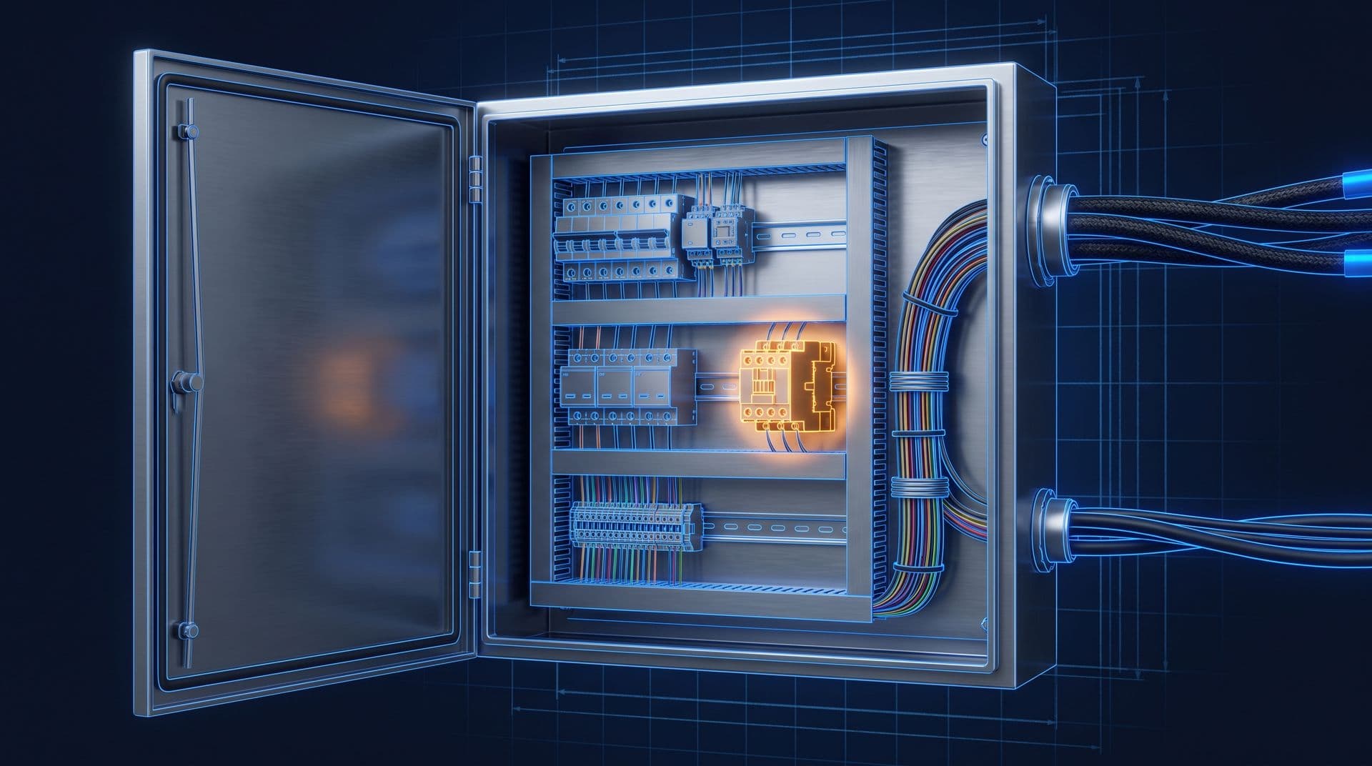
Part 9 of 11 in Cobler's Building Electrical Fundamentals course. New here? See the course page.
Part 8 ended with the pumps and fans that restart after a power cut. Each of them is switched by a control panel. What is inside an electrical control panel, and how does a small control circuit switch a large pump motor on and off?
In the chiller plant room of the office tower, there is a row of grey steel cabinets, one beside each chilled-water pump. Each has a red-and-yellow handle and a few lamps and buttons on the door. Every so often, one of them makes a loud clunk, and a few seconds later a pump starts to hum. This part explains what is behind that door and what made the clunk, so that the parts, lamps and labels on a panel make sense to you.
You will not open a panel. The doors stay closed because the parts inside work at 400 V and 230 V. Opening, testing and repairing panels is work for an authorised, Suruhanjaya Tenaga (ST) registered competent person, such as the site's chargeman.
What is inside an electrical control panel? Two circuits
An electrical control panel holds two separate circuits that work together. One does the heavy work and the other decides when that work happens.
The power circuit carries the energy to the equipment. In the office tower, it takes 400 V three-phase power (see Three-Phase Power Explained in the Electricity Fundamentals course) from the chiller plant sub-switchboard to the pump motor. Its cables are thick because they carry a large current, often tens of amps.
The control circuit makes the decisions. It runs through the buttons, the lamps, the controller and the small relays, and it carries only a small current. It never drives the pump itself. It only switches the parts that do.
The control circuit works at a lower or separate voltage, and which one depends on the panel:
- 24 V DC (direct current) is common for electronic controllers, sensors and many newer panels.
- 230 V AC (alternating current) is also common, especially for contactor coils and lamps in building starter panels. The pump panels in the office tower use 230 V AC control.
A 24 V circuit carries a lower shock risk. A 230 V control circuit is at the same voltage as a wall socket, so it is just as dangerous. In both cases the panel also contains 400 V power parts.
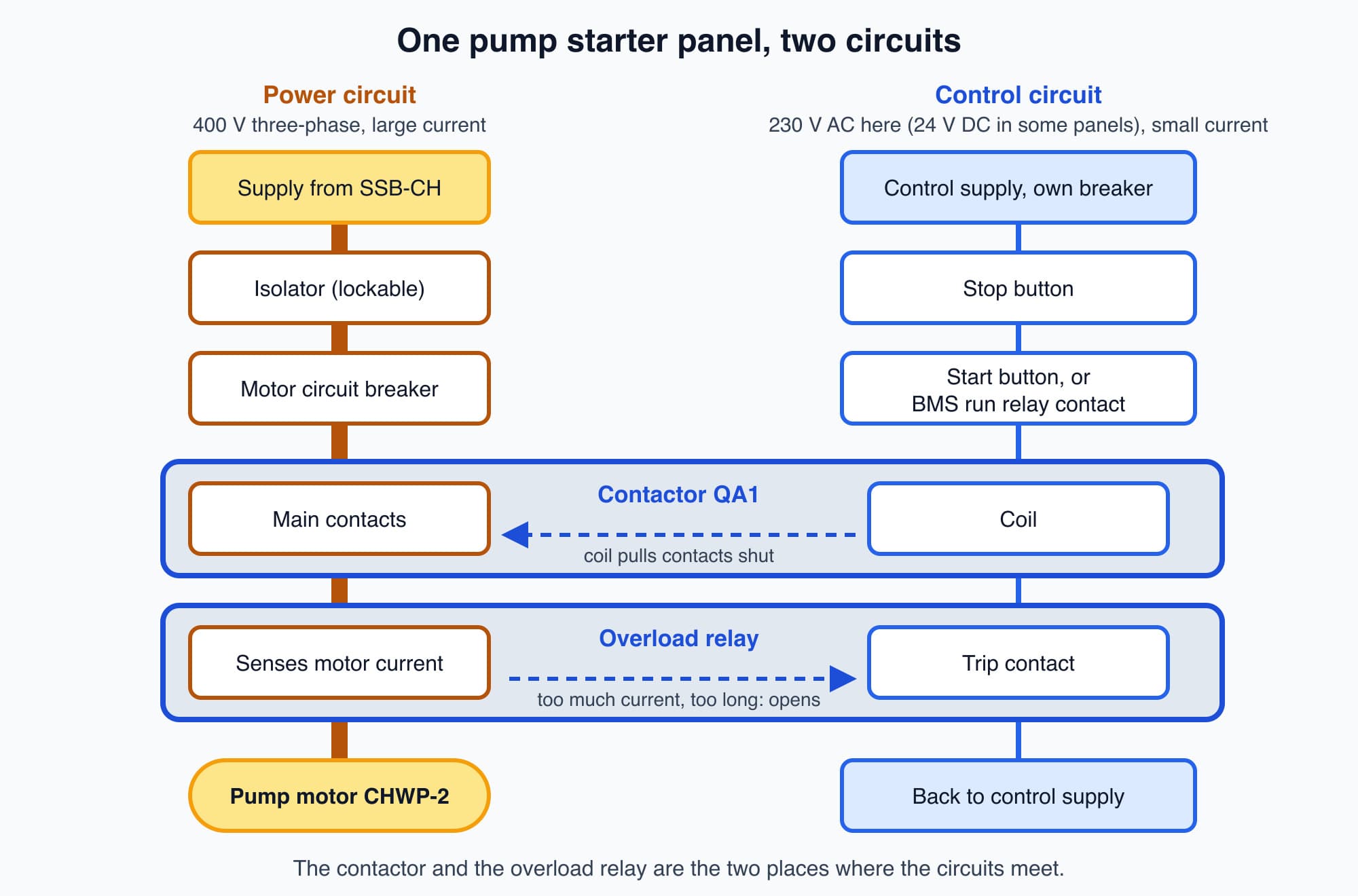
The power circuit feeds the pump; the control circuit decides when it runs, and the two meet at the contactor and the overload relay.
Once you see the two circuits, the panel starts to make sense. The thick cables and large blocks belong to the power circuit. The thin wires and slim modules belong to the control circuit. The most useful parts to understand are the ones where the two circuits meet, because that is where a small decision switches a large load. The first of these is the part that clunks.
The clunk is a contactor closing
The clunk is a contactor closing. A contactor is a switch that is operated by an electromagnet instead of a hand.
Inside a contactor there are four main parts:
- a coil of wire wound around an iron core
- a movable iron block called the armature
- a spring that holds the armature away from the core
- the main contacts: one pair of copper contacts for each of the three phases, with one side of each pair moving with the armature
When the control circuit sends current through the coil, the iron core becomes a magnet. The magnet pulls the armature towards it against the spring. The main contacts move with the armature and close, which completes the 400 V circuit to the motor. The clunk you hear is the armature hitting the core.
When the control circuit stops the current in the coil, the core is no longer a magnet. The spring pushes the armature back, the main contacts open and the motor stops. You may hear a second, softer clunk as this happens.
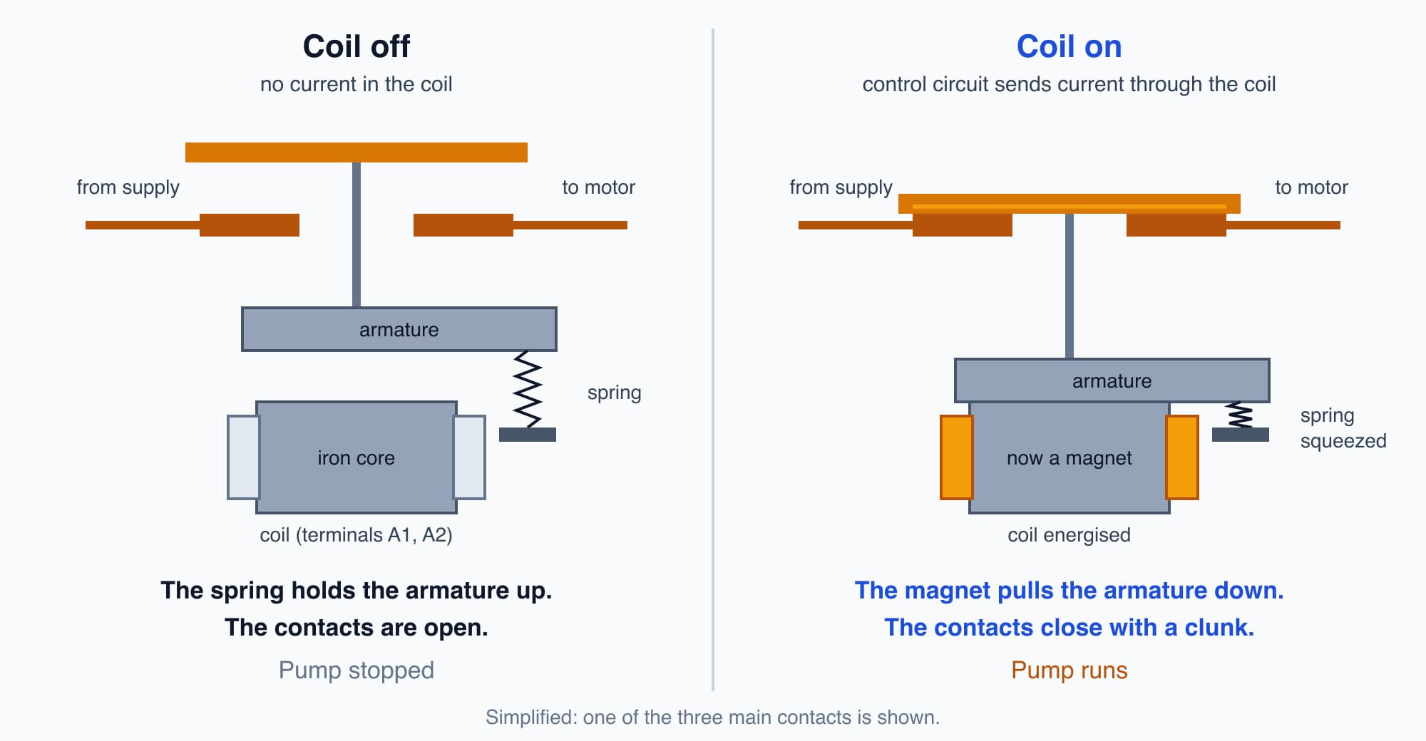
With no coil current, the spring keeps the contacts open; with coil current, the magnet pulls them shut.
So a small current in the coil controls a much larger current in the main contacts. That is how the control circuit switches the power circuit.
A relay works the same way on a smaller scale. It is also a coil that pulls an armature to move a set of contacts, but its contacts are small and switch control signals rather than motors. A contactor has larger contacts built to switch motor current. If you understand one, you understand the other. Much of a control panel is made of these electromagnetic switches at two sizes.
What tells the contactor to close?
The contactor closes when something in the control circuit completes the path to its coil. In a building panel, that can be a person or a controller.
Push-buttons on the door. A local Start button lets a person start the pump at the panel, and a Stop button stops it. Part 10 shows how these buttons are wired so that the pump keeps running after you let go of Start.
A controller. Most of the time, nobody presses Start. A controller decides when the pump should run. It reads inputs, such as whether the pump is running or has tripped, and sets outputs, such as a run command. In the office tower, the controller belongs to the building management system (BMS), the computer system that runs the air conditioning plant, ventilation and lighting schedules. In other buildings and in factories, the controller may be a programmable logic controller (PLC), a small industrial computer that does the same job. Both usually have rows of small lights showing which inputs are on and which outputs are active.
An interface relay. Controller outputs usually work at 24 V and can switch only a small current. They do not drive the pump contactor coil directly. Instead, the controller's output energises a small relay, and that relay's contact completes the contactor's coil circuit. In the office tower, this is the BMS run relay, labelled KF1. It keeps the controller's low-voltage electronics separate from the 230 V control circuit.
So the chain in the tower is: the BMS decides the pump should run, the BMS output energises relay KF1, the KF1 contact closes, the contactor coil is energised, and the contactor connects the pump motor to the 400 V supply.
What protects the pump motor?
Two devices protect the motor and its cable against two different problems.
The circuit breaker handles short circuits. A motor circuit breaker sits on the power circuit before the contactor. It opens quickly if a very large fault current flows, for example if a cable is damaged. Circuit Breaker Types (Part 4) explains how breakers do this and how they are chosen.
The overload relay handles slow overheating. A motor that draws somewhat more than its rated current for a long time can overheat without ever causing a short circuit. The thermal overload relay, usually clipped below the contactor, protects the motor against this. In the common thermal type, the motor current heats small strips made of two bonded metals. The strips bend as they warm up, and if the current stays too high for too long, they bend far enough to operate a trip mechanism. (Electronic overload relays do the same job by measuring the current directly.)
The overload relay does not cut the heavy power circuit itself. Instead, it opens a small contact wired into the control circuit. That cuts the current to the contactor coil, the contactor opens and the motor stops. Many panels also use a second overload contact to light a TRIP lamp on the door.
A contactor, an overload relay and short-circuit protection together make a motor starter. Each pump in the office tower has one.
An overload relay has a reset button. Whether anyone other than the competent person may press it is set by the site's written procedure. A trip means something drew too much current, and the cause needs finding before the pump runs again. Part 11 works through a pump trip step by step.
How a panel is stopped and made safe
Stopping a pump and making it safe to work on are two different things.
Stop and emergency stop. The Stop button and any red mushroom-head emergency stop button are wired directly into the control circuit. Pressing one breaks the path to the contactor coil, so the contactor opens and the motor stops. An emergency stop is hardwired this way on purpose: it does not ask the controller's software to react, so it still works if the software fails. Some emergency stop circuits also pass through a dedicated safety relay.
The isolator. Stopping the motor does not make the panel safe to work on. After a stop, the power circuit up to the contactor is still live, and so is the control circuit. The isolator, the switch behind the red-and-yellow handle, disconnects the incoming supply and can be locked in the off position.
Even then, a panel can contain circuits fed from somewhere else, such as a control supply or a BMS signal from another panel. That is why making a panel safe is a job for the competent person. They isolate, lock off and prove the circuits dead with a tester before any work starts.
Some pumps have a variable speed drive instead
Some panels also control the motor's speed, not just whether it runs. That job is done by a variable speed drive (VSD), also called a variable frequency drive (VFD). It is a larger module, usually with cooling fins.
A contactor can only switch a motor fully on or fully off. A VSD changes the frequency of the power it sends to the motor, and the motor's speed follows the frequency. In the office tower, the secondary chilled-water pumps have VSDs, so they can slow down when the building needs less chilled water. A VSD creates electrical noise, so it is usually kept apart from the sensitive control wiring.
Worth knowing: Running a fan or a pump slower can save a lot of energy, because the power it needs falls steeply as its speed drops. The saving is smaller when a pump must push against a fixed pressure, for example to lift water to a certain height.
Numbers on every wire link the panel to its drawings
Every wire in a well-built panel can be traced to a drawing, because the wire and the drawing carry the same number.
Where the panel's internal wiring meets the cables that run out to the pump, the buttons and the BMS, each wire lands on a terminal block, a row of screw terminals clipped onto a metal rail. Every wire carries a small printed sleeve, called a ferrule, with a number on it. The same number appears on the panel's wiring drawings.
This lets a competent person who has never seen the panel before find any wire on the drawing, and any drawing line in the panel. Reading those drawings is the subject of the next part.
What comes next
A panel's wiring drawing shows the control circuit as a set of simple lines, one for each decision: "if Stop is not pressed and the overload has not tripped, and Start is pressed, energise the contactor coil." The next part, How to Read Control Wiring Diagrams, uses the control circuit of the tower's chilled-water pump to answer one question: how do you read a control wiring diagram?
Check your understanding
- Why does the overload relay stop the pump by opening a small contact in the control circuit, rather than cutting the power circuit directly? The contactor already exists to switch the heavy power circuit. When the overload contact opens, the current to the contactor coil stops, the contactor opens, and the motor stops. The overload relay only needs a small contact, and the same contact arrangement can also light a TRIP lamp.
- After someone presses the emergency stop, is the pump panel safe to work on? No. The emergency stop opens the contactor, so the motor stops, but the power circuit up to the contactor and the control circuit are still live. Only a competent person who has isolated the supply, locked it off and proved the circuits dead can work inside the panel.
Recap: A control panel holds a power circuit, which carries 400 V three-phase power to the equipment, and a control circuit, which decides when it runs. Control circuits are often 24 V DC, and 230 V AC is also common. A contactor is a switch closed by an electromagnet; its closing is the clunk. A relay is the same idea at a smaller size. A controller such as a BMS or PLC gives the run command through an interface relay. A breaker protects against short circuits; an overload relay protects the motor against sustained overcurrent by opening a contact in the control circuit. Stopping is not isolation. A VSD varies motor speed. Numbered wires link the panel to its drawings.
Go deeper on video (optional)
These two videos show real control panels and contactors. The first uses a factory PLC panel, but the parts are the same as in a building starter panel.
"What is an Electrical Control Panel? (PLC Panel Basics)" by RealPars
"What is Contactor?" by Zebra Learnings
If motors or breakers are new to you, How Electric Motors Work in the Electricity Fundamentals course and Circuit Breaker Types are good refreshers.
This is Part 9 of 11 in Cobler's Building Electrical Fundamentals course. Previous: When the Mains Fails: Generators, ATS and UPS. Next: How to Read Control Wiring Diagrams.
Cobler builds CobiNeural, a platform that shows a facility team its building's energy, water and indoor air data as live numbers across the whole site. To see how your building performs, talk to us.
FAQ
Frequently asked questions
Ask us about this topic
Something in this article you want to dig into — or a situation in your own building it doesn't quite cover? Send us your question. We don't run public comments; the team replies to you directly by email.