Blog
Inside the Consumer Substation: The Locked Room
Every building has a locked room marked DANGER 11,000 V that almost nobody has seen inside. Walk the consumer substation left to right: the ring main unit, the vacuum breaker, the transformer, the meter and the battery that lets the breaker trip when the power fails.
 Tan Kok XinBuilding Electrical Fundamentals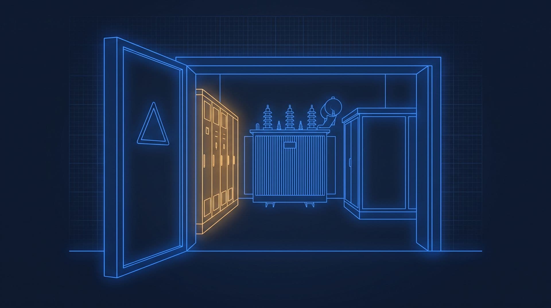
Part 2 of 11 in Cobler's Building Electrical Fundamentals course. New here? See the course page.
Part 1 traced the office tower's power up the tree, from a pantry kettle to one of the building's two transformers. Those transformers sit in the tower's own substation, behind a locked door. What is in that room, in what order does the power pass through it, and who is allowed to touch it?
Which buildings this part is for. A consumer substation is found in buildings that take their supply at 11,000 volts (11 kV), like the office tower. If your building takes a 400/230 V supply from a TNB (Tenaga Nasional Berhad) substation outside, like the shoplot, you can skim this part. The transformer that feeds you works the same way, but TNB owns and operates it.
In the office tower, the locked door is near the loading bay. It carries a yellow warning triangle, a lightning bolt and the words DANGER 11,000 VOLTS. Staff walk past it every day, and few of them have seen inside. Everything plugged into a socket anywhere in the building gets its power through the equipment behind that door.
This part walks through the room one machine at a time. How the Malaysia Electricity Grid Reaches Your Plug in the Electricity Fundamentals course explains how the 11 kV supply reaches the building.
What is inside a consumer substation?
A consumer substation is a short chain of equipment. It takes TNB's 11,000 V supply, measures it, protects it, and hands the building a supply at 400/230 V. The power passes through the parts in this order:
- TNB's 11 kV cables arrive and connect to a ring main unit (RMU), a set of switches.
- Metering equipment measures the supply for TNB's bill.
- A vacuum circuit breaker (VCB) protects the cable and transformer that follow it.
- The transformer brings the voltage down from 11 kV to 400 V.
- Heavy low-voltage (LV) cables carry the 400 V supply to the main switchboard (MSB).
A battery cabinet keeps the protection working if the supply fails, and an earthing system connects all the metalwork together. The office tower has two transformers, each with its own VCB. The diagram shows one of the two.
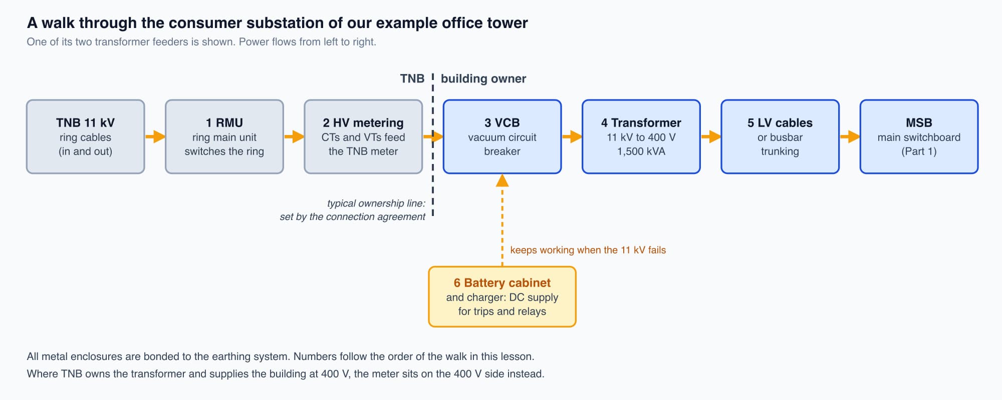
The walk through the tower's substation, in the order the power flows; the dashed line shows a typical position of the ownership line.
The ring main unit connects the building to TNB's ring
The first piece of equipment, next to the incoming cables, is the ring main unit (RMU). It exists because TNB does not feed the building from a dead end.
TNB's 11 kV cables run as a ring. The cable leaves a TNB substation, passes through one building's substation after another, and returns. Power can reach the building from either direction around the ring. If one section of cable fails, TNB can open switches on each side of the damaged section and supply the building from the other direction.
Inside the RMU's sealed tank are two ring switches, one for the cable on each side of the ring, and a third connection that feeds the building. The ring switches are load-break switches. They can open and close while normal load current is flowing, so a section of the ring can be isolated for work. They are not built to interrupt a short circuit. The RMU also has an earthing switch. It is interlocked so that it can close only after the switch for that cable is open. Closing it connects the isolated cable to earth, so that it can be made safe before anyone works on it. In the office tower, the RMU is TNB equipment, operated by TNB's authorised staff.
The TNB meter measures the supply at 11 kV
The tower's TNB billing meter measures the supply on the 11 kV side, before the transformers. A meter cannot be connected directly to 11,000 V, so two kinds of instrument transformer feed it smaller copies of the voltage and current:
- Voltage transformers (VTs) step 11 kV down to 110 V.
- Current transformers (CTs) scale the current down to a small standard value, typically 5 A or 1 A. How Electricity Meters Work, in Cobler's electricity bill course, explains how a CT works, and current transformers and their ratios covers how they are chosen.
At 11 kV the currents are quite small. The size of a transformer or a supply is given in kilovolt-amperes (kVA), which combines voltage and current (kW, kVA and kVAR in the Electricity Fundamentals course explains why). For every 1,000 kVA, the current in each line is about 52 A at 11 kV, but about 1,443 A at 400 V. The higher the voltage, the smaller the current for the same supply.
For the office tower:
- Each 1,500 kVA transformer at its full rating draws about 79 A at 11 kV and delivers about 2,165 A at 400 V.
- At the building's maximum demand, about 1,739 kVA, the current at the 11 kV meter is about 91 A.
The whole bill depends on these CTs and VTs, so TNB seals the metering cubicle. Breaking the seal is tampering with the meter, which nobody in the building is allowed to do.
Not every building is metered at 11 kV. In some buildings, TNB owns the transformer, in a TNB substation on the site or down the street, and supplies the building at 400 V. The meter then sits on the 400 V side. A large LV supply still needs CTs, because the current is high; a small one, such as the shoplot's, may be connected straight through the meter.
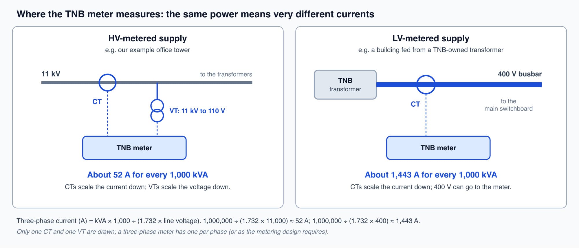
The same 1,000 kVA is about 52 A at 11 kV but about 1,443 A at 400 V, which is why the meter's position changes the equipment it needs.
The vacuum circuit breaker interrupts faults at 11 kV
After the metering, the power reaches the building's own 11 kV switchgear. For each transformer there is a vacuum circuit breaker (VCB). It protects the cable and the transformer that follow it, and it is the device that can interrupt a short circuit at 11 kV. Protection relays measure the current and tell the breaker when to open.
Opening a circuit that carries a large current is difficult. When the contacts separate, the current keeps flowing across the gap as an arc: a path of very hot, electrically conducting gas. At 11 kV, an arc can keep thousands of amps flowing. A VCB opens its contacts inside a sealed ceramic bottle with the air pumped out. In a vacuum there is almost no gas to keep an arc going.
The supply is alternating current (AC), so the current passes through zero twice in every cycle. At the next zero after the contacts part, the arc goes out and does not restart.
Worth knowing: On Malaysia's 50-hertz supply, the current passes through zero 100 times a second, so a VCB never waits long for the moment it needs. Once the arc goes out, the vacuum gap recovers its insulating strength within microseconds. The contacts move only about a centimetre, and the bottle is smaller than a vacuum flask.
The transformer brings 11,000 volts down to 400
The largest machine in the room is the distribution transformer. It does the voltage change that the whole substation exists for.
How Transformers Work explains the principle: two coils on one iron core, with no moving parts. Here the transformer steps the 11 kV supply down to 400 V between phases, which is 230 V between any phase and neutral, the voltage at an ordinary socket.
In an office building, the transformer is often a cast-resin dry-type unit rather than an oil-filled one, because a dry transformer carries much less fire risk indoors. Sizes range from a few hundred kVA up to a couple of thousand. The office tower has two 1,500 kVA transformers. The rating is in kVA rather than kW because the transformer's heating depends on the current it carries, whatever the power factor of the load.
Heavy cables carry the 400 V supply to the main switchboard
From the transformer's low-voltage terminals, heavy cables or busbar trunking (solid copper or aluminium bars in a metal casing) carry the 400 V supply a short distance to the main switchboard (MSB). The MSB is the trunk of the building's electrical tree from MSB, SSB and DB.
These conductors are large because the current at 400 V is large. Each of the tower's transformers can deliver about 2,165 A at its full rating, compared with about 79 A on its 11 kV side.
A battery cabinet keeps the protection working when the supply fails
The substation also contains a cabinet of batteries with a charger. It supplies direct current (DC), commonly at 30, 48 or 110 V, to the breakers' trip coils and closing coils and to the protection relays.
The reason is simple. A breaker must be able to open during a fault, and a fault often makes the supply voltage collapse. If the trip coil took its power from the 11 kV line it protects, it could lose that power at the moment it is needed. The battery gives the protection its own supply, independent of the one it protects.
A trip circuit supervision relay checks the trip coil's wiring continuously. If a wire in the trip circuit has broken, the breaker would not open when told to, so the relay raises an alarm.
Earthing, and the line between TNB's equipment and the building's
Earthing. Every metal enclosure in the substation is connected to the earthing system. This gives fault current a planned path, so that protection can detect the fault and disconnect it, and it limits the voltage on metalwork a person might touch. The earthing design, including how the transformer's neutral point is earthed, is set by the consulting engineer to meet TNB's and ST's requirements. Some substations use separate earth electrode systems for different purposes; the drawings and test records show which. In the office tower, the building's circuits use TN-S earthing from the transformers. Neutral and Earth: Why They Stay Separate, Part 6 of this course, explains what that means for neutral and protective earth.
Before anyone works on isolated equipment, an authorised person connects it to earth, using the earthing switch or portable earths clamped on after the equipment has been proved dead.
Ownership. The room has a line through it that you cannot see. In the office tower, TNB owns the incoming ring cables, the RMU and the metering. The building owner owns the installation from its 11 kV switchgear onward: the VCBs, the transformers, the cables and the MSB. The exact position of the line is set by the connection agreement, so it varies from site to site. In a building where TNB owns the transformer, the building's installation starts on the 400 V side instead.
Who may operate the equipment in this room
Nobody should open, switch or work on anything in the substation without the right authorisation. Under the Electricity Regulations 1994, electrical installations are operated and worked on by competent persons holding a certificate of competency from Suruhanjaya Tenaga (ST), the Energy Commission, such as a chargeman. Operating 11 kV switchgear requires a certificate that covers high-voltage work; a low-voltage certificate is not enough.
Equipment on TNB's side of the line is operated by TNB. So the locked door does two jobs: it keeps people away from 11,000 V, and it enforces who is legally allowed to touch what is inside.
What an operator can safely watch and report
An operator can learn a lot about the substation's health without opening any panel or operating any switch.
- Fault passage indicators on the RMU are small flags or lamps that show when fault current has passed through a cable. They help TNB find which section of the ring has failed. If one shows an indication, record it and report it; do not reset it yourself.
- Transformer temperature. Transformers run warm by design, and many have a temperature indicator. A reading that is rising compared with past readings at the same load means something has changed, and should be reported. The load that warms the transformer also sets the building's maximum demand, the highest 30-minute average power in the month, which TNB charges for on the office tower's bill. Cobler's electricity bill course explains that charge.
- Battery charger alarms, unusual noise, a burning smell, or a substation door left open should also be reported at once.
An infrared (thermographic) survey finds loose connections, which show up as hot spots before they fail. It is a valuable check, but it can require panels to be opened, so it is arranged by the competent person and carried out under the site's safety rules. A Trip Is a Clue, Part 11 of this course, covers how to record and report what you see.
Optional detail: The line current of a three-phase supply is kVA × 1,000 ÷ (1.732 × line voltage). The 1.732 is the same factor that links 230 V and 400 V in Three-Phase Power Explained. For 1,000 kVA that gives 1,000,000 ÷ (1.732 × 11,000) ≈ 52 A at 11 kV and 1,000,000 ÷ (1.732 × 400) ≈ 1,443 A at 400 V. Older substations used breakers filled with sulphur hexafluoride (SF6) gas to put out the arc; SF6 works well but is a powerful greenhouse gas, which is why vacuum is now the usual choice for new 11 kV breakers. Where an installation is operated in two or more shifts, Regulation 62 of the Electricity Regulations 1994 requires the competent person arrangement on each shift.
What comes next
The substation is the top of the building's electrical drawing: the first few symbols before every board, riser and socket. The next part, How to Read a Single Line Diagram, shows the whole office tower on one sheet, starting from the RMU and meter you have just met. It answers one question: what is a single line diagram, and how do you read it?
Check your understanding
- Why does the tower's TNB meter need voltage transformers and current transformers? The meter measures on the 11 kV side, and a meter cannot be connected directly to 11,000 V. VTs step the voltage down to 110 V. CTs scale the current, about 91 A at the tower's maximum demand, down to a small standard value such as 5 A or 1 A.
- Why does a substation have its own battery cabinet? A breaker must be able to open during a fault, and a fault often makes the supply collapse. The battery supplies DC to the trip coils and relays independently of the supply they protect, so the breaker can still open.
Recap: A consumer substation takes an 11 kV supply and hands the building 400/230 V. In the office tower, TNB's ring cables enter an RMU, the supply is metered at 11 kV through VTs and CTs, a VCB protects each transformer, and each transformer steps 11 kV down to 400 V for the MSB. At 11 kV the current is about 52 A per 1,000 kVA, compared with about 1,443 A at 400 V. A battery keeps the protection working when the supply fails. The connection agreement sets the ownership line, and only competent persons with the right certificate operate the equipment.
Go deeper on video (optional)
These two videos show real substation equipment. Some of the equipment and voltages they show differ from a Malaysian office building, and you do not need them for the next part.
"Substation equipment and their functions" by TheElectricalGuy
"Identify equipment in a substation" by Aaron Danner
This is Part 2 of 11 in Cobler's Building Electrical Fundamentals course. Previous: MSB, SSB and DB: Your Building's Electrical Tree. Next: How to Read a Single Line Diagram.
Cobler builds CobiNeural, a platform that shows a facility team its building's energy, water and indoor air data as live numbers across the whole site. To see how your building performs, talk to us.
FAQ
Frequently asked questions
Ask us about this topic
Something in this article you want to dig into — or a situation in your own building it doesn't quite cover? Send us your question. We don't run public comments; the team replies to you directly by email.