Blog
How Control Loops Work: Setpoints, Feedback and Closing the Loop
Learn how an HVAC control loop setpoint works: sense the value, compare it to a target, then act. Open-loop vs closed-loop, feedback and deadband explained.
 Tan Kok XinBuilding Automation & BMS Fundamentals
Part 4 of 16 in Cobler's Building Automation and BMS Fundamentals course. New here? See the course page.
In Part 3 we saw that AHU-12A, the air handling unit on level 12 of the office tower, has its own controller wired to seven I/O points. That left a question: what does the controller's program actually do with its points, and how does it use a temperature reading to decide where to put the chilled water valve? The answer is a control loop: measure, compare with a target, act to reduce the difference, and repeat.
A useful comparison is taking a shower. You turn the tap, feel the water, and turn the tap again until the temperature is right. You measure with your skin, decide in your head and act with your hand, then check again. A building management system (BMS) does the same with a sensor, a controller and a valve.
Three words: setpoint, process variable and error
To describe a control loop, we need names for its parts. We keep the simple version from Part 1, where AHU-12A's valve holds the return air from the level 12 offices at a target. (Part 5 switches to the loop AHU-12A really uses, which holds the supply air at 14 °C. The ideas in this part are the same for both.)
- The setpoint is the target: the value you want. For AHU-12A it is 24 °C.
- The process variable is the value being measured right now. For AHU-12A it is the return air temperature, the temperature of the air coming back from the offices. Say it reads 26 °C, because the offices have filled with people and the afternoon sun is on the windows.
- The error is the gap between the two.
There are two ways to write the error, and they differ only in sign. In this course we use error = setpoint − process variable. For AHU-12A that is 24 − 26 = −2 °C. With this convention, a negative error on a cooling loop means the air is warmer than the target, so the controller opens the chilled water valve further. Some controllers and textbooks use process variable − setpoint instead, which gives +2 °C for the same situation. The size of the gap is the same; only the sign flips. When you work on a real controller, check which convention it uses.
The controller's job is to bring the error towards zero. As the offices cool from 26 °C towards 24 °C, the error shrinks from −2 °C towards zero, and the controller opens the valve less eagerly. When the error reaches zero, the controller stops changing the valve and holds it at about the opening that keeps the air at 24 °C. It does not close the valve, because the offices still need that much cooling.
Open-loop control acts without checking the result
To see why checking the result matters, look first at a system that does not check.
Imagine a fan wired to a simple timer that runs it for one hour and then stops. This is open-loop control: the system follows a fixed instruction and never checks whether the instruction is working. The timer does not know whether the room is cool or hot. It runs the fan for one hour whether the room is empty, full, sunny or shaded.
Open-loop control is cheap and simple, and it works when the result is predictable. A toaster runs on a timer, and so does a basic garden sprinkler. But when conditions change, for example the room fills with people or the sun moves round the building, an open-loop system cannot notice and cannot correct.
Closed-loop control checks the result and corrects
Now replace the timer with a thermostat. A thermostat measures the room, compares it with the setpoint and adjusts the cooling. Then it measures again to see whether the adjustment worked, and keeps adjusting until the room reaches the setpoint.
Measuring the result of your own action and using it to decide the next action is called feedback, and a system that uses it is under closed-loop control. The loop is "closed" because the output (cooler air) comes back round to the input (the sensor), completing a circle.
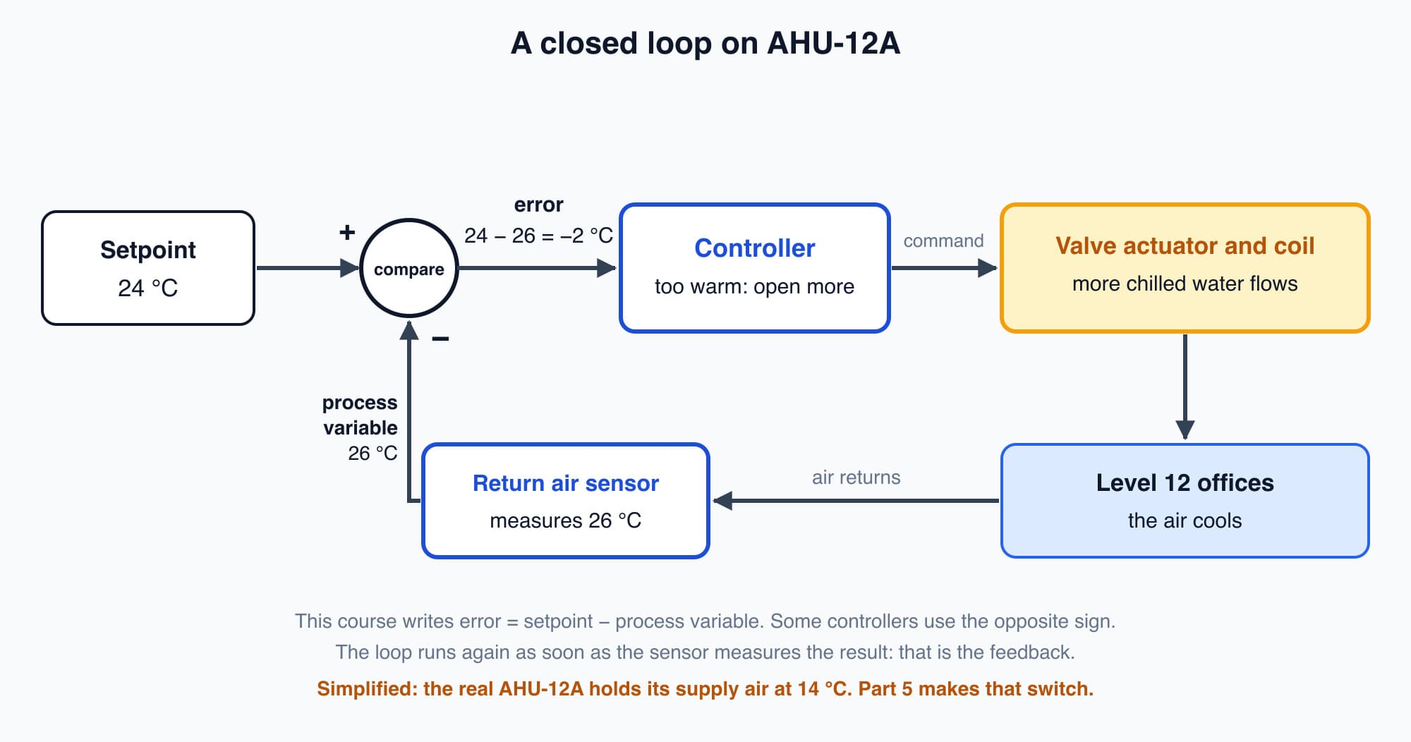
AHU-12A's closed loop: the controller compares the 24 °C setpoint with the measured 26 °C, acts on the valve, and the sensor measures the result.
This is why people call a BMS "smart". It is not clever the way a person is clever. It responds to what a sensor measures, not to an assumption. If the offices warm up faster than expected, the loop cools harder. If they are already cool, it backs off. Almost everything a BMS does, from one room to a whole chiller plant, is a version of this closed loop.
A modulating loop should not chase sensor noise
Real sensor readings are never perfectly steady. AHU-12A's return air sensor might read 24.0, then 24.1, then 23.9, then 24.05 °C, because of small eddies in the airflow and tiny variations in the sensor's electrical signal. These small, fast wobbles are called noise. They do not mean the offices are really getting warmer or cooler.
If the controller reacted hard to every wobble, it would keep moving the chilled water valve a little open, a little closed, and open again. The valve would never settle. That extra movement wears out the valve actuator and does nothing for comfort.
For a modulating loop like AHU-12A's valve, which can sit at any position, controllers deal with noise in two ways:
- Filtering. The controller smooths the reading, for example by averaging it over a short time, so small fast wobbles have little effect.
- Tuning. The controller is set to respond gently to small errors and more firmly to large or lasting ones. Part 5 explains how.
Noise is different from a problem called hunting, where the whole loop swings steadily back and forth because it is tuned too aggressively. Part 5 explains hunting and how to fix it.
A deadband gives on/off equipment, staging and alarms a zone of "close enough"
Some equipment cannot sit halfway. It is either on or off. For these, the usual tool is a deadband: a small band around the setpoint where the controller leaves things as they are.
Suppose one of the fan coil units in our example tower's lobby has a simple on/off chilled water valve. Its setpoint is 24 °C, with a deadband of one degree, from 23.5 to 24.5 °C:
- When the lobby warms to 24.5 °C, the valve opens and the fan coil unit cools.
- The valve stays open while the temperature falls through the band.
- When the lobby cools to 23.5 °C, the valve closes.
- The valve stays closed while the temperature rises back through the band, until it reaches 24.5 °C again.
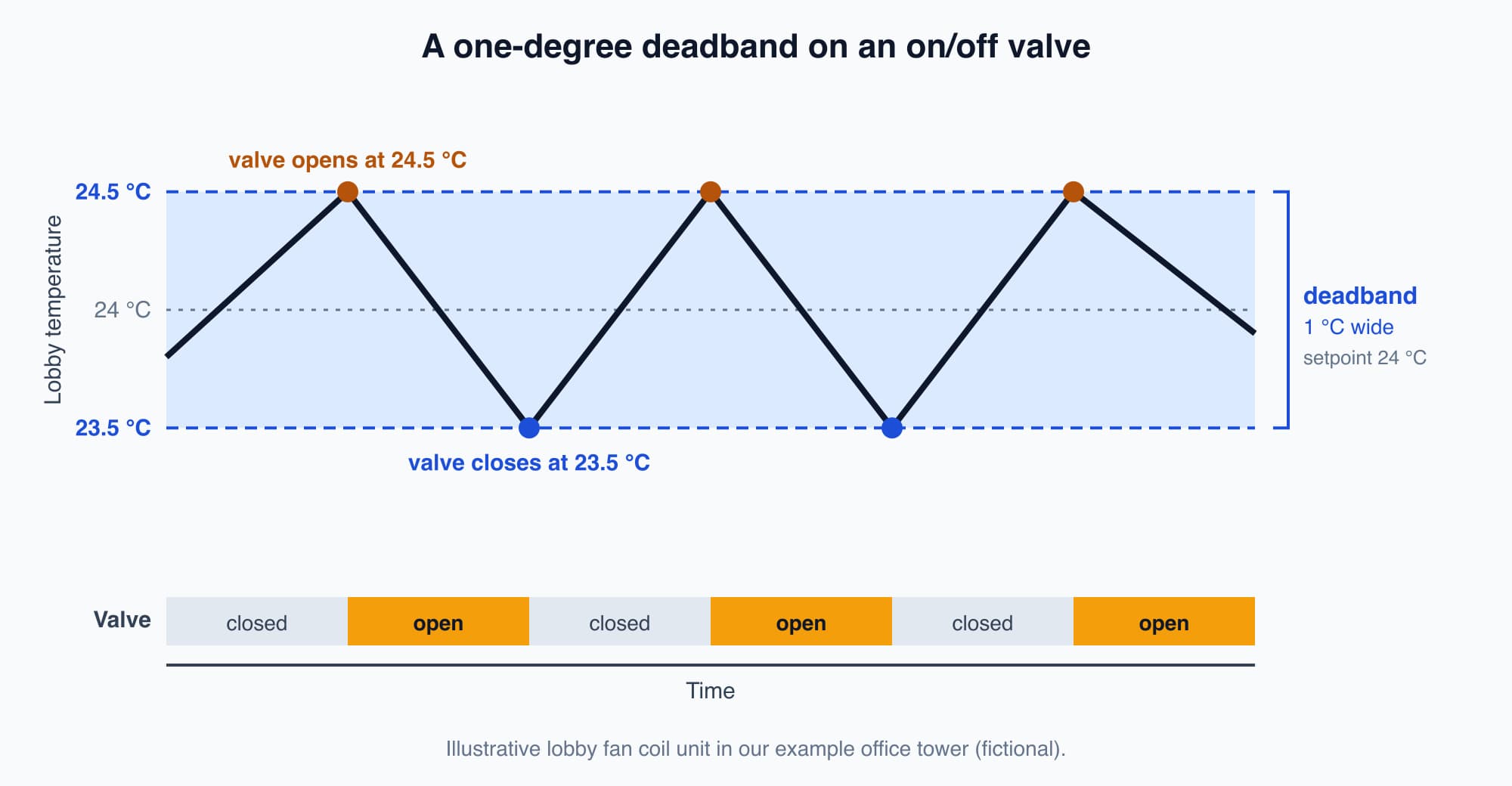
With a one-degree deadband, the on/off valve opens at 24.5 °C and closes at 23.5 °C, instead of clicking on and off around exactly 24 °C.
Without the deadband, the valve would switch every time the reading crossed 24 °C. With noise on the sensor, that could mean switching many times a minute, which wears out the valve and any equipment it starts. Both ends of this band sit inside the 23 to 26 °C comfort range from ICOP IAQ 2010, the indoor air quality code introduced in Part 2, so the lobby stays within the acceptable range.
Deadbands are also used in two other places you will meet later in the course:
- Staging. A chiller plant should not start another chiller for a small, brief rise in load and stop it a minute later. Part 12 shows how staging uses a band.
- Alarms. An alarm that clears the moment the value dips below its limit will flicker on and off. Part 8 covers alarm settings like this.
One loop, repeated thousands of times
Here is the whole loop in order:
- A sensor measures the process variable: what is actually happening.
- The controller compares it with the setpoint to find the error.
- The controller moves an actuator (a valve or damper), or switches equipment on or off, to reduce the error.
- The action changes the air or water, the sensor measures the new value, and the loop runs again.
One loop holds the level 12 offices at 24 °C. Another holds the chilled water leaving the plant at its setpoint. Another holds the air pressure in a duct steady. A large BMS runs thousands of these simple loops, each measuring, comparing and adjusting.
Worth knowing: The controller does not need to know about sunshine, people or the weather forecast. It only needs two numbers, where the air is and where it should be, and it keeps adjusting until they match. That is why the same simple loop works on a sunny afternoon, a rainy morning and a crowded meeting day.
What comes next: how hard should the controller push?
So far the controller knows the size and sign of the error. It still has to reach the setpoint without overshooting or swinging back and forth. The next part, PID Control Explained Simply, explains the three ways a controller judges that, and what goes wrong when it is tuned badly. It starts from this question: for a given error, how far should the controller move the valve?
Check your understanding
- AHU-12A's setpoint is 24 °C and its return air reads 25 °C. Using this course's convention, what is the error, and what should the controller do? Error = setpoint − process variable = 24 − 25 = −1 °C. On a cooling loop, a negative error means the air is too warm, so the controller opens the chilled water valve further.
- Why does AHU-12A's modulating valve loop use filtering and tuning, while the lobby fan coil unit's on/off valve uses a deadband? A modulating valve can move by small amounts, so the controller smooths the noisy reading and responds gently to small errors. An on/off valve can only open or close, so without a band it would switch every time the temperature crossed 24 °C. The deadband (23.5 to 24.5 °C) stops it switching until the temperature has really moved.
Recap: A control loop measures the process variable, compares it with the setpoint to find the error, and acts to reduce the error, then repeats. In this course, error = setpoint − process variable, so a negative error on a cooling loop means too warm. Open-loop control follows a fixed instruction without checking; closed-loop control uses feedback to correct itself. Modulating loops deal with sensor noise through filtering and tuning. Deadbands give on/off equipment, staging and alarms a small "close enough" zone so they do not switch back and forth.
Go deeper on video (optional)
This animated video shows the same loop: measuring the process variable, comparing it with the setpoint and acting on the error. It is optional: you do not need it for the next part.
RealPars walks through the core control-loop cycle in plain, animated terms — measuring the process variable, comparing it to the setpoint, and acting on the error to close the loop.
This is Part 4 of 16 in Cobler's Building Automation and BMS Fundamentals course. Previous: Controllers, DDC and I/O Points: The Brain Behind the BMS. Next: PID Control Explained Simply: Why a Valve Overshoots, Hunts or Settles.
Cobler builds CobiNeural, a platform that shows a facility team its building's energy, water and indoor air data as live numbers across the whole site. To see how your building performs, talk to us.
FAQ
Frequently asked questions
Ask us about this topic
Something in this article you want to dig into — or a situation in your own building it doesn't quite cover? Send us your question. We don't run public comments; the team replies to you directly by email.