Blog
Controllers, DDC and I/O Points: The Brain Behind the BMS
What is DDC (direct digital control)? A plain-language guide to controllers, the four I/O point types, point count, and why BMS control is distributed.
 Tan Kok XinBuilding Automation & BMS Fundamentals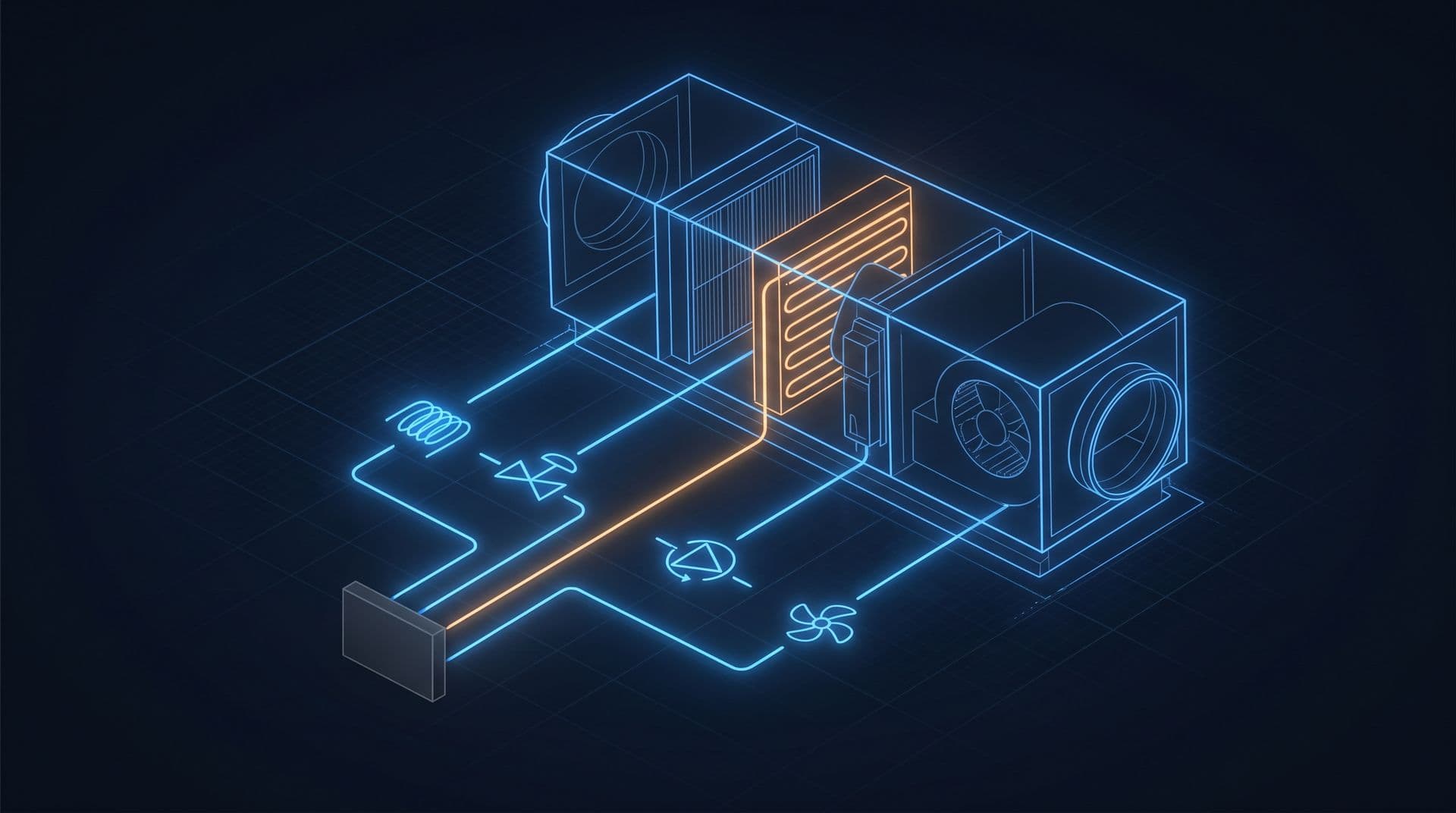
Part 3 of 16 in Cobler's Building Automation and BMS Fundamentals course. New here? See the course page.
Part 2 gave AHU-12A its sensors and actuators and left one question: what sits between the sensors and the actuators and makes the decisions, and how is each device connected to it? In the office tower those decisions are made all day without anyone touching a switch: a supply fan slows down as a meeting room empties, or a pump trips and a standby pump starts within seconds.
The part of the building management system (BMS) that makes them is the controller. In modern buildings the controller is almost always a DDC controller. This part explains what DDC, direct digital control, means, and introduces the unit the whole BMS industry uses to count its work: the I/O point. We finish with the full point list for AHU-12A, the air handling unit we follow through this course.
What is DDC? Direct digital control means a small computer makes the decisions
Before DDC, buildings were controlled by mechanical and pneumatic devices. Thermostats contained metal strips that bent as they warmed, and control signals were sent as changes in compressed-air pressure through small copper tubes. The logic was built into the hardware. To change how the system behaved, someone had to adjust or replace a device.
Direct digital control (DDC) replaces that mechanical logic with a small computer running a program. "Digital" here does not mean "connected to the internet" or "has a touchscreen". It means the decision is made by a microprocessor running a program, the same kind of chip found in a phone or a washing machine, built to survive in a plant room.
So a DDC controller is a small computer dedicated to controlling equipment. It does three things, over and over, for years:
- It reads its inputs, for example a chilled water temperature.
- It runs its control program, for example comparing that temperature with a target and working out how far off it is.
- It drives its outputs, for example telling a valve to open a little more.
This is the sense, decide, act loop from Part 1, now running inside one box. The main advantage is that the behaviour lives in software, not hardware. To change how a building is controlled, an engineer edits the program instead of refitting tubes and devices. A change that once took a week of pneumatic fitting is now a configuration change.
The style of logic inside these controllers (measure, compare with a target, correct, repeat) is called feedback control. Part 4 explains it for building equipment.
The I/O point: one connection between the controller and the equipment
A DDC controller is only useful because it is wired to real equipment. Each single connection between the controller and the physical world is called an I/O point (input/output point), or simply a point. One sensor, one valve command, one status signal or one start command is one point.
Every point is one of four types. Two questions decide which:
- Is information coming in to the controller (an input) or going out from it (an output)?
- Is the signal analogue (a value that varies across a range) or digital (on or off)? Part 2 explained the difference.
That gives:
- AI, analogue input. A varying value coming in. Example: a temperature sensor reading 12.3 °C on a chilled water pipe.
- AO, analogue output. A varying command going out. Example: telling a valve actuator to sit at 45% open, anywhere between shut and fully open.
- DI, digital input. An on/off status coming in. Example: a pump reporting "I am running", or a filter switch reporting "I am dirty".
- DO, digital output. An on/off command going out. Example: "start this fan" or "stop this fan".
Almost everything a BMS does can be described as a combination of these four point types. They have been the standard way to describe commercial building controls for decades.
AHU-12A's point list
Here are the points on AHU-12A, the air handling unit that cools the east half of level 12 in the office tower. An air handling unit is the large box with a filter, a cooling coil and a fan that pushes cooled air into the offices. These are the same sensors and actuators we placed on it in Part 2, now sorted by point type.
Point on AHU-12A | Type | What it does |
|---|---|---|
Supply air temperature | AI | Measures the air leaving the AHU towards the offices |
Return air temperature | AI | Measures the air coming back from the offices |
Filter differential pressure | AI | Rises as the filter gets dirty |
Chilled water valve position | AO | Tells the valve actuator how far to open |
Supply fan speed | AO | Tells the fan's variable-speed drive how fast to run |
Fan status | DI | Confirms the fan is actually running |
Run command | DO | Tells the fan to start or stop |
That is seven points: three AI, two AO, one DI and one DO. The filter is measured as a differential pressure (an AI), which shows how dirty it is. A cheaper design would use a filter switch (a DI) that only says "clean" or "dirty".
The run command (DO) and the fan status (DI) are separate points on purpose. The command is what the controller asked for; the status is what actually happened. If the controller commands the fan to run but the status stays "off", something is wrong, such as a tripped drive. Part 6 explains why it matters which device the status signal comes from, and later parts use this pair often.
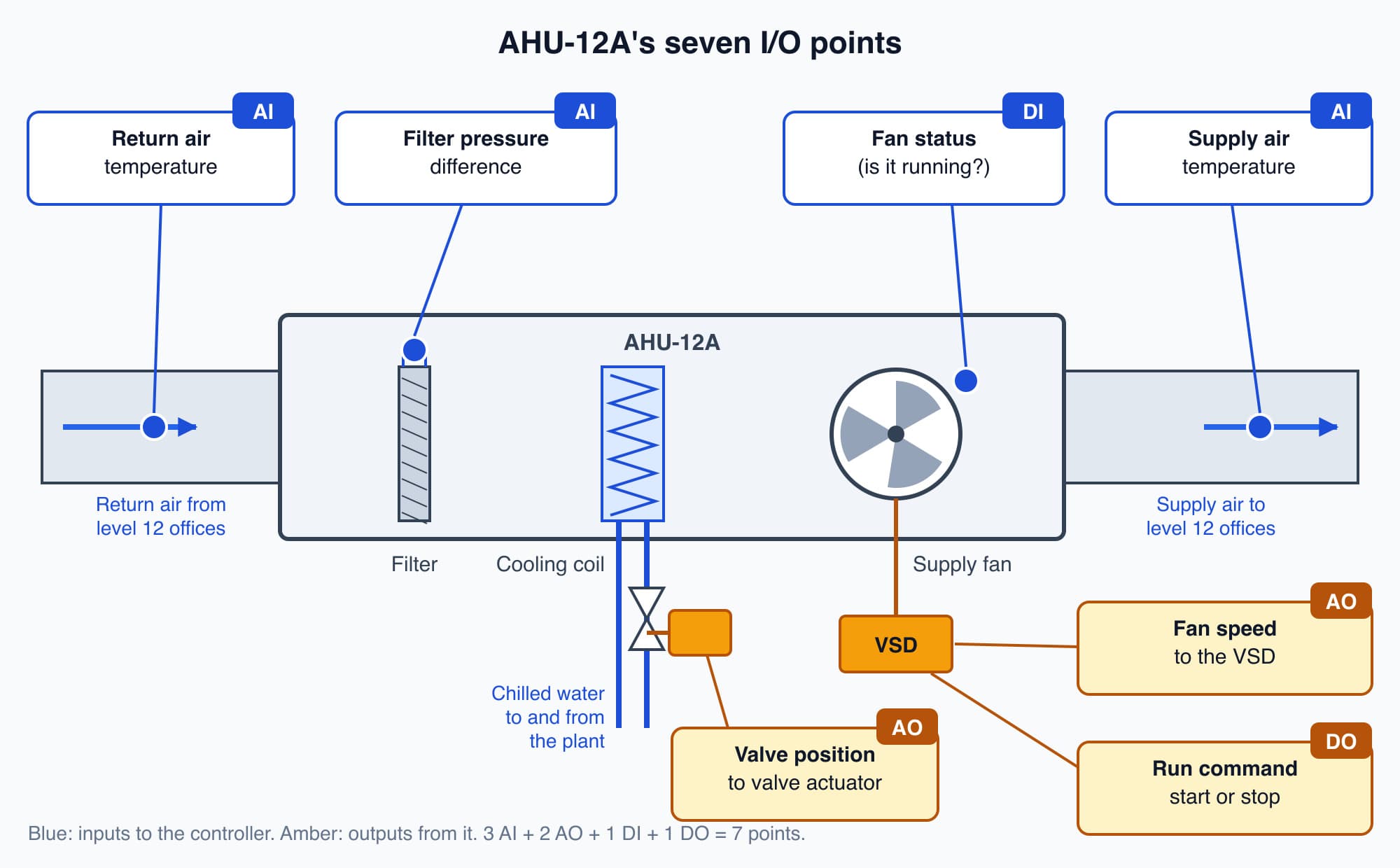
AHU-12A's seven I/O points: every wire between the unit and its controller is one of the four point types.
(These outputs are small signals, not the power for the fan motor itself, as Part 2 explained.)
Counting points sizes and prices a BMS
Because almost every wire into or out of a controller is one point, counting points is how the BMS industry measures a job. A building is described as an 800-point building or a 2,400-point building. For a sense of scale: if each of the office tower's 20 office floors had two AHUs like AHU-12A, the AHUs alone would add up to 40 × 7 = 280 points, before the chiller plant, pumps, fans and meters.
The point count drives three things:
- Scope. The point schedule, also called the points list, is the master document that says exactly what will be monitored and controlled. If something is not on the point schedule, the BMS cannot see it or change it.
- Sizing. Each controller has a fixed number of inputs and outputs, so the point count tells the designer how many controllers are needed.
- Pricing. Hardware, wiring, labour and commissioning time all grow roughly with the number of points, so tenders are often priced per point.
A controls engineer starts a design with the point schedule. If a point is missed, for example a fan status or a meter reading, that capability does not exist in the finished building, however good the software is. Writing an accurate point schedule and the controller layout around it is core building automation work. It is what Cobler's Automation Services team scopes at the start of a project.
A BMS is many controllers arranged in layers
A BMS is not one big computer in a control room. It is a hierarchy of many controllers, usually in three layers.
1. Field controllers. At the bottom, on or beside each piece of equipment (an AHU, a chiller, a set of pumps), sits a field controller. It is sometimes called an application-specific or unitary controller. This is the DDC controller for that one machine. Its I/O points are wired directly to the equipment, and it runs that equipment's control loops. In our example tower, AHU-12A has its own field controller with the seven points above.
2. Supervisory controllers. Above the field layer sit supervisory controllers. Each one looks after a floor, a zone or a whole plant, such as the chiller plant room. Their job is coordination: deciding how many chillers run, sharing information between field controllers, and passing data up and down. One supervisory controller may look after a dozen or more field controllers.
3. The head-end. At the top is the head-end: a server and one or more operator workstations, usually in the facilities office. This is where people see the building: floor plans, trends, alarms and setpoints that an operator can change.
If the network fails, each field controller keeps running its equipment
Suppose the network cable to the chiller plant is cut by accident, or the head-end server is switched off for maintenance. If the whole building depended on one central computer, control would stop everywhere at once.
In a distributed DDC system, that does not happen. Each field controller holds its own control program and its own setpoints. If the network drops or the server stops, the controller keeps controlling its own equipment, as long as it still has power. AHU-12A's controller keeps holding its air temperature, and the chiller plant's controllers keep making chilled water.
What you lose is the view from the head-end and the coordination between controllers. Operators cannot see or change anything remotely, and any decision that needs information from another controller falls back to whatever local setting the controller was programmed to use until the network returns.
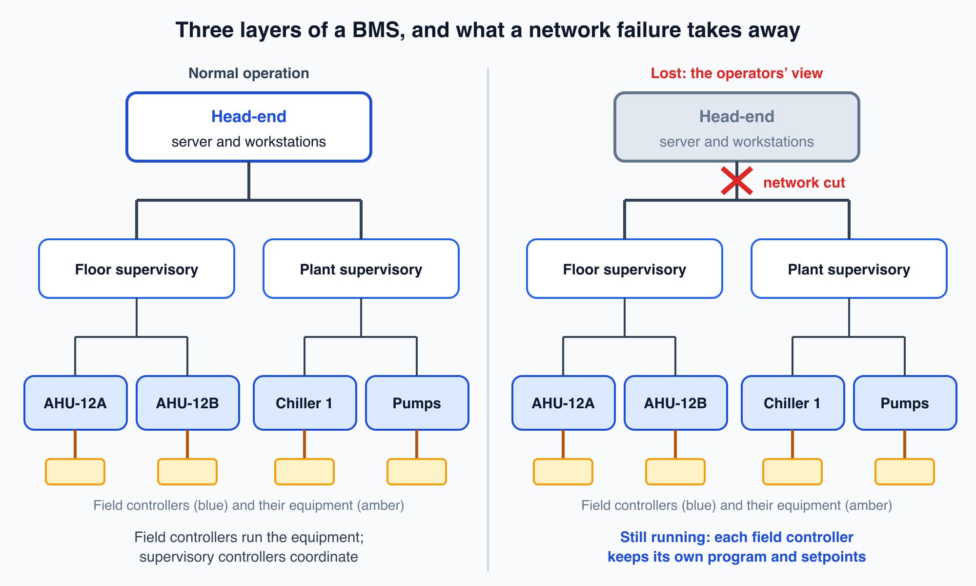
When the network is cut, the head-end loses its view, but each field controller keeps running its own equipment.
This is called resilience by design. The control logic is placed down at the edge, close to the machines, so that no single failure stops the whole building. Part 11 covers who looks after the network and how a building recovers when it fails.
Worth knowing: A wall thermostat at home, or the controller inside a split unit, is also a small digital controller. It has one analogue input (the room temperature), a target you set, and in effect one digital output (call for cooling): a point count of a handful. A commercial BMS is hundreds or thousands of these controllers, coordinated by supervisory controllers and visible from one head-end.
What comes next: the control loop inside the controller
We now know what a controller is and how it connects to AHU-12A through seven points. The next part, How Control Loops Work, explains setpoints, measurements, error and feedback. It answers the question this part leaves open: what does the controller's program actually do with its points, and how does it use a temperature reading to decide where to put the chilled water valve?
Check your understanding
- Classify these AHU-12A points: supply air temperature, chilled water valve position, fan status, run command. Supply air temperature is an analogue input (AI): a varying value coming in. Valve position is an analogue output (AO): a varying command going out. Fan status is a digital input (DI): on or off, coming in. Run command is a digital output (DO): on or off, going out.
- The network cable to the head-end is cut. Does AHU-12A stop cooling level 12? No. Its field controller holds its own program and setpoints and keeps controlling the AHU as long as it has power. The operators lose their view of it and the coordination with other controllers until the network is restored.
Recap: Direct digital control (DDC) means a small dedicated computer makes control decisions in software instead of mechanical or pneumatic hardware. Each connection between a controller and the equipment is an I/O point of one of four types: AI, AO, DI or DO. AHU-12A has seven points: three AI, two AO, one DI and one DO. Point count sets the scope, size and price of a BMS. A BMS is layered: field controllers run the equipment, supervisory controllers coordinate, and the head-end is the operators' window. Because each field controller holds its own logic, the equipment keeps running if the network or head-end fails.
Go deeper on video (optional)
This video shows controllers and sensors working together in a real BMS, including the layered arrangement described earlier. It is optional: you do not need it for the next part.
RealPars gives a clear, plain-language walkthrough of how a building management system's controllers and sensors work together to run HVAC, lighting and more.
This is Part 3 of 16 in Cobler's Building Automation and BMS Fundamentals course. Previous: BMS Sensors and Actuators: A Building's Senses and Muscles. Next: How Control Loops Work: Setpoints, Feedback and Closing the Loop.
Cobler builds CobiNeural, a platform that shows a facility team its building's energy, water and indoor air data as live numbers across the whole site. To see how your building performs, talk to us.
FAQ
Frequently asked questions
Ask us about this topic
Something in this article you want to dig into — or a situation in your own building it doesn't quite cover? Send us your question. We don't run public comments; the team replies to you directly by email.