Blog
PID Control Explained Simply: Why a Valve Overshoots, Hunts or Settles
PID control explained simply: how proportional, integral and derivative decide how hard a BMS pushes a valve, and why sloppy tuning makes a room keep swinging.
 Tan Kok XinBuilding Automation & BMS Fundamentals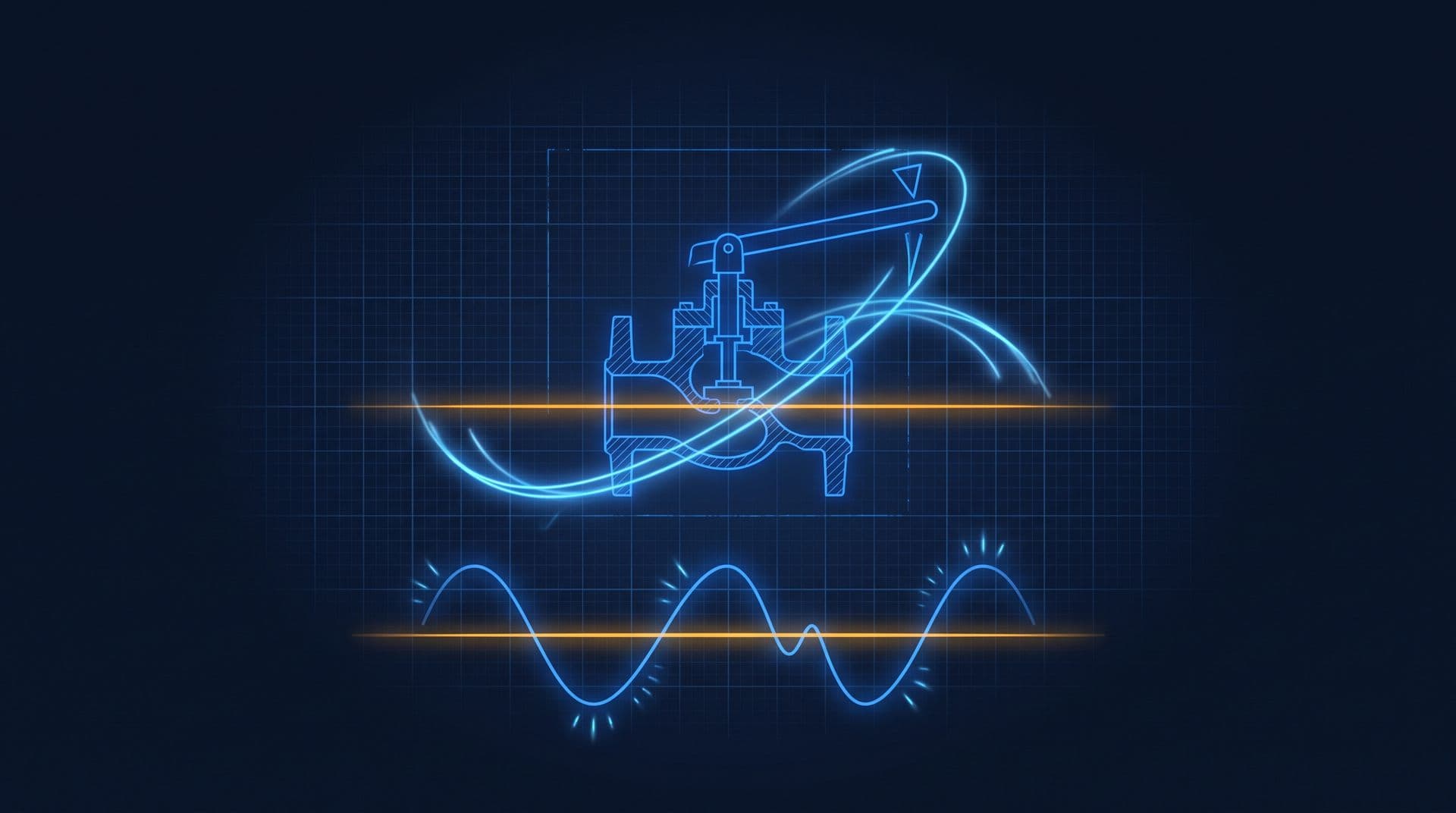
Part 5 of 16 in Cobler's Building Automation and BMS Fundamentals course. New here? See the course page.
In Part 4 we saw that a control loop measures a value, compares it with a setpoint and moves something to close the gap. That left a question: for a given error, how far should the controller move the valve? If it moves too much, the temperature overshoots and swings. If it moves too little, the temperature never quite reaches the target. The usual answer is a calculation called PID control. This part is PID control explained simply, without any calculus, using one loop on AHU-12A.
A useful comparison is steering a car. If you drift a little towards the lane line, you turn the wheel a little. If you drift a lot, you turn it more, and you ease off as the car comes back to the centre. A building controller makes the same kind of decision many times a minute.
The controller turns the error into a valve position
From this part on, we use the loop AHU-12A really runs. In Parts 1 and 4 the valve held the return air at 24 °C, to keep the first examples simple. In the real AHU-12A, air is blown across a coil filled with chilled water, and the cooled air, called supply air, goes out to the floor. A sensor measures the supply air temperature. The controller compares it with a setpoint of 14 °C and positions the chilled water valve: more open means more chilled water through the coil and colder supply air. (The variable air volume (VAV) boxes on the floor then look after each room's own 24 °C target. Part 13 covers them.)
The gap between the setpoint and the measurement is the error. This course uses the convention from Part 4:
$$\text{error} = \text{setpoint} - \text{measured value}$$
If the supply air is 16 °C and the setpoint is 14 °C, the error is 14 − 16 = −2 °C. The minus sign means "too warm". The controller is set up so that a too-warm error opens the chilled water valve further. (Some controllers calculate measured value minus setpoint for cooling, so a too-warm error comes out positive. The sign convention only tells the controller which way to move the valve. What matters is that "too warm" leads to "open the valve".)
PID is the rule that turns the error into a valve position. Its three letters, P, I and D, are three questions the controller asks about the error:
- P, proportional: how big is the error right now?
- I, integral: how long has the error lasted?
- D, derivative: how fast is the error changing?
The controller adds the three answers together to get the valve command. The next three sections take one question at a time.
(For a more mathematical treatment of the same idea, see the separate article feedback control and PID explained. You do not need it for this course.)
Proportional control pushes harder the bigger the error
Proportional control moves the valve in proportion to the error. A bigger error gives a bigger valve opening. As the supply air cools and the error shrinks, the valve closes back by the same rule. This is the steering wheel from the opening: a small drift gets a small correction, a large drift gets a large one.
The setting that decides how strongly it reacts is called the gain. As an illustration, say AHU-12A's controller opens the valve 50% for every 1 °C of error. At 1 °C too warm it asks for 50% open, and at 0.2 °C too warm it asks for 10% open.
Proportional control on its own has one weakness: it leaves a small, permanent gap between the setpoint and the measurement. The reason is that the coil always needs some chilled water. Warm air from the floor and fresh air from outside keep arriving at the coil, so the valve must stay partly open to hold the supply air cold. With proportional control, the only thing that holds the valve open is the error itself. If the error reached zero, the controller would ask for 0% open, the coil would warm up, and the error would come back.
So the loop settles at the point where the error is just big enough to hold the valve where the coil needs it. If the coil needs the valve about 30% open, then with a gain of 50% per degree the error settles at 0.6 °C. AHU-12A would hold 14.6 °C instead of 14.0 °C. Engineers call this leftover gap offset (sometimes "droop"). A higher gain makes the offset smaller, but as the section on hunting shows, too high a gain makes the loop swing.
Integral control removes the offset by adding up the error over time
Integral control looks at how long the error has lasted. It keeps a running total of the error over time. While the supply air sits 0.6 °C too warm, the total keeps growing, and the integral part keeps adding a little more valve opening. It only stops adding when the error is zero, so it slowly pushes the supply air all the way down to 14.0 °C and removes the offset.
A useful comparison is a person who notices "it has been slightly too warm for ten minutes now, so I should open the valve a bit more than I first thought". That running memory is what closes the last fraction of a degree.
Proportional and integral together are called PI control. Proportional gives a quick reaction to the size of the error, and integral removes the offset so the loop lands on the setpoint. Most temperature, pressure and flow loops in buildings run on PI control.
Integral control can also cause trouble. If it builds up its total too quickly, it keeps opening the valve after the supply air has already reached 14 °C, because the total it has built up takes time to run down. The supply air then overshoots and goes colder than the setpoint, and the loop has to correct back the other way.
Derivative control eases off as the error closes quickly
Derivative control looks at how fast the error is changing, not how big it is. Its job is to anticipate. A useful comparison is parking a car: as you approach the wall, you brake before the bumper touches it, because you can see the gap closing quickly. If the supply air temperature is falling quickly towards 14 °C, the derivative part reduces the valve opening early to prevent the overshoot.
Derivative control is less common in buildings for two reasons:
- It reacts to sensor noise. A sensor reading always wobbles a little. Because derivative control reacts to change, it turns every small wobble into a valve movement, which makes the valve twitch.
- Most building loops change slowly. Air, water, ducts and concrete take minutes to warm up or cool down, so there is little sudden change to anticipate. On slow temperature loops, the derivative part is usually switched off.
In practice:
- P only is simple and reacts quickly, but leaves an offset. It can be acceptable where a small, steady error does not matter.
- PI is the standard for most building air-conditioning loops. It removes the offset and lands on the setpoint.
- Full PID is kept for the few faster loops, such as some pressure or flow loops, where anticipating an overshoot helps.
Hunting is a loop that keeps swinging instead of settling
In this course, hunting means a loop that keeps swinging above and below its setpoint in a steady, repeating wave instead of settling. On AHU-12A you would see the valve open wide, close, open wide again, and the supply air temperature rise and fall around 14 °C every few minutes, hour after hour.
Hunting is most often caused by tuning that is too aggressive. The controller reacts so strongly that it pushes the temperature past the setpoint, then reacts strongly the other way and pushes it past again. A gain that is too high, or an integral part that builds up too quickly, can turn a steady loop into a hunting one. This is like a driver who over-corrects at every lane line and weaves down the road.
Hunting is more than a comfort problem. Every swing drives the valve actuator, the small device from Part 2 that physically moves the valve. An actuator designed to move occasionally is now moving all the time, and its gears, linkage and the valve seat wear out much sooner. Across hundreds of loops in a large building, this becomes a real maintenance cost.
(Other faults can make a trend look similar, such as a valve that sticks and then jumps. Part 8 shows how to tell tuning problems apart from sensor and equipment faults.)
A trend line shows which of these a loop is doing
A trend is a graph of a point's value over time, recorded by the BMS (building management system). Plotting the supply air temperature against the 14 °C setpoint shows how a loop is behaving. The four common shapes are below.
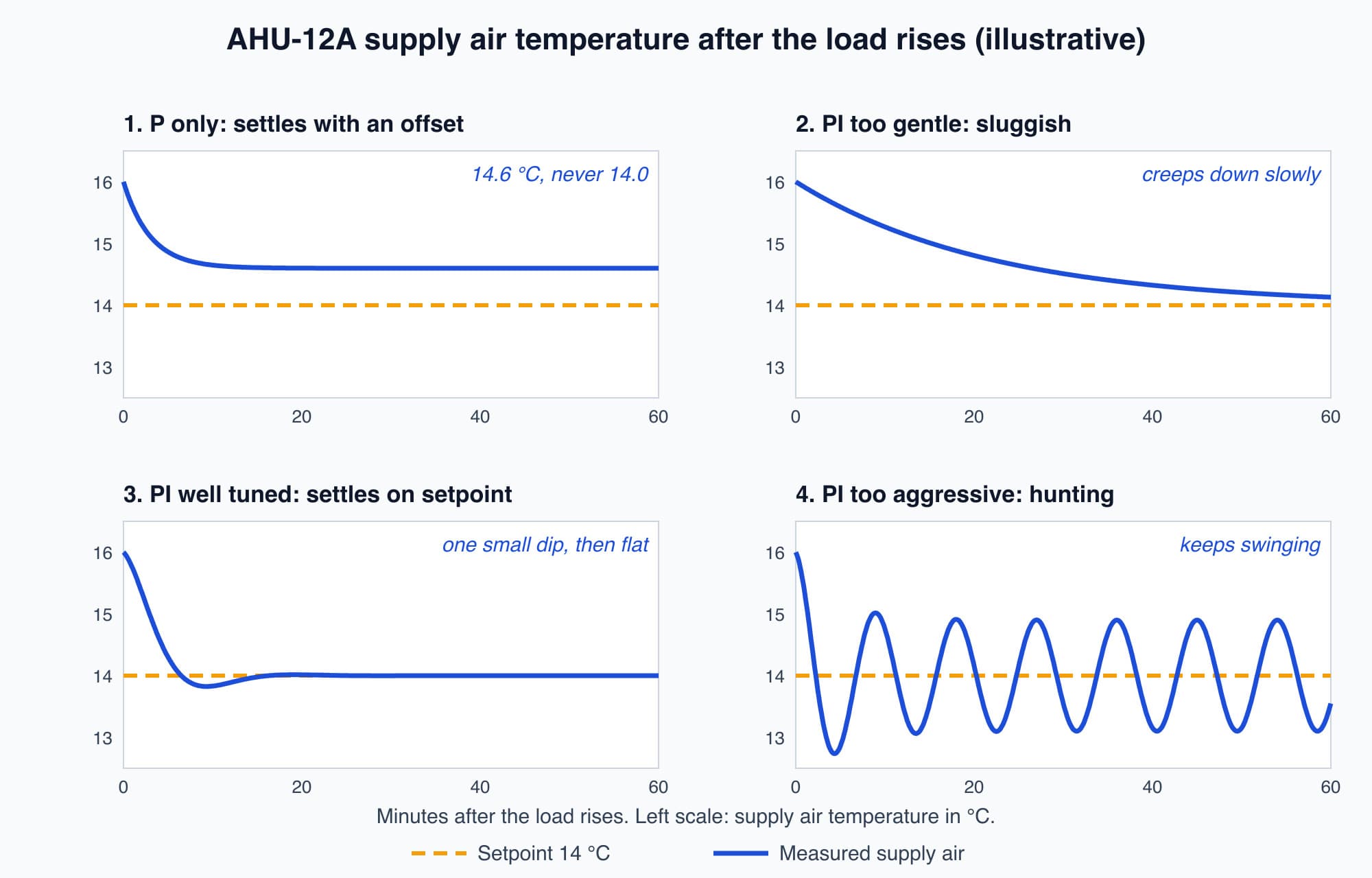
Four ways AHU-12A's supply air loop can respond when the load rises: each shape points to a different tuning setting (illustrative traces).
- P only, with offset. The temperature settles quickly but stays flat just above the setpoint, around 14.6 °C. The fix is to add integral action.
- PI, too gentle (sluggish). The temperature creeps towards 14 °C very slowly. On a hot afternoon the load changes before the loop catches up, so it may never quite get there.
- PI, well tuned. The temperature comes down promptly, may dip slightly below the setpoint once, and then holds flat on 14 °C.
- PI, too aggressive (hunting). The temperature overshoots, swings back past the setpoint and keeps swinging in a regular wave.
When you look at a trend, it helps to plot the valve position on the same graph. In a hunting loop, the valve position swings in step with the temperature.
Tuning balances a quick response against a steady one
Tuning means choosing the gain and the integral setting (and the derivative setting, if it is used) for each loop. You are balancing two opposite failures:
- Too aggressive: the loop overshoots and hunts. Comfort is unsteady and the actuator wears out.
- Too gentle: the loop is sluggish. It reaches the setpoint slowly or not at all, and occupants say the floor is stuffy even though the controller is "working".
Good tuning is quick enough to reach the setpoint promptly and calm enough to stay there. There is no single correct setting, because each loop drives different equipment. A small VAV box responds in seconds, while a chilled water plant takes many minutes. This is why loops are tuned during commissioning, one at a time, by someone who changes the setpoint, watches the trend and adjusts the settings until the loop settles cleanly.
It is also why complaints like "the temperature keeps swinging" or "the floor never cools down" are often tuning problems rather than broken hardware. The sensor, valve and controller can all be healthy while the settings are wrong. Retuning loops so they settle, and making controllers work together rather than against each other, is part of automation and controls work. Before retuning, it is still worth checking the sensor and the valve, because a faulty one can look like a tuning problem.
Worth knowing: Despite the name, most building loops are P or PI, and full PID is the exception. On slow temperature loops the derivative part is usually switched off, because air, water and concrete change temperature over minutes and the derivative part would mostly react to sensor noise.
What comes next: many loops working together
So far we have looked at one loop on its own. A building runs many loops at once, and they must start, stop and hand over in the right order. The next part, What Is a Sequence of Operation in a BMS?, explains the written plan that tells AHU-12A and the chiller plant what to do, when and in what order. It answers three questions this part leaves open: when should AHU-12A start, what must be true before its loops are allowed to run, and what should it do when a part fails?
Check your understanding
- AHU-12A's supply air loop uses proportional control only. It settles at 14.6 °C with a 14 °C setpoint. Why, and what would remove the gap? The coil needs the valve partly open all the time, and with proportional control only the error holds it open. The loop settles where the error is just big enough to keep the valve where the coil needs it, here 0.6 °C. Adding integral action removes the gap, because the integral part keeps adding valve opening for as long as any error remains.
- A trend shows the supply air temperature swinging above and below 14 °C every few minutes, with the valve swinging open and closed at the same rhythm. What is the most likely cause, and why does it matter? The loop is hunting, most likely because its tuning is too aggressive (too high a gain or too fast an integral). It matters because comfort is unsteady and the constant movement wears out the valve actuator. The usual fix is to retune the loop more gently, after checking that the sensor and valve are working properly.
Recap: PID turns the error (setpoint minus measured value) into a valve command by asking three questions. Proportional reacts to how big the error is, but on its own leaves an offset. Integral reacts to how long the error has lasted and removes the offset. Derivative reacts to how fast the error is changing, and is usually switched off on slow temperature loops. Most building loops are P or PI. A loop tuned too aggressively hunts; one tuned too gently is sluggish. Loops are tuned at commissioning by watching their trends.
Go deeper on video (optional)
This short video shows the three parts of PID acting on a valve loop, which matches the P, I and D sections above. It is optional.
RealPars walks through what proportional, integral and derivative each do in plain terms, using a valve-and-setpoint control loop as the example.
This is Part 5 of 16 in Cobler's Building Automation and BMS Fundamentals course. Previous: How Control Loops Work: Setpoints, Feedback and Closing the Loop. Next: What Is a Sequence of Operation in a BMS?.
Cobler builds CobiNeural, a platform that shows a facility team its building's energy, water and indoor air data as live numbers across the whole site. To see how your building performs, talk to us.
FAQ
Frequently asked questions
Ask us about this topic
Something in this article you want to dig into — or a situation in your own building it doesn't quite cover? Send us your question. We don't run public comments; the team replies to you directly by email.