Blog
What Is a Sequence of Operation in a BMS?
A sequence of operation is the plain-English recipe telling a BMS what runs when, in what order. Learn how interlocks, staging and modes unify a plant.
 Tan Kok XinBuilding Automation & BMS Fundamentals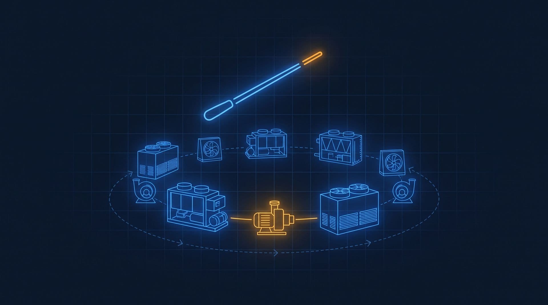
Part 6 of 16 in Cobler's Building Automation and BMS Fundamentals course. New here? See the course page.
In Part 4 and Part 5 we saw how one control loop holds one value, such as AHU-12A's supply air at 14 °C. That left three questions: when should AHU-12A start, what must be true before its loops are allowed to run, and what should it do when a part fails? The building management system (BMS) answers them from a written plan called the sequence of operation.
A useful comparison is a recipe. A kitchen assistant with ingredients and appliances but no recipe does not know what goes first, how long to wait or when the dish is done. This part explains the sequence of operation that HVAC (heating, ventilation and air conditioning) designers write, using AHU-12A and the chiller plant of the office tower.
A sequence of operation is a written "when X, do Y" plan
A sequence of operation is a list of plain-English rules of the form when X happens, do Y. It says what runs, in what order, under what conditions and with what settings. A person who does not write code should be able to read it and know how the equipment will behave.
A fragment for AHU-12A might read:
When level 12 east enters occupied mode, start the AHU-12A supply fan. When the fan status confirms that the fan is running, enable the chilled water valve loop to hold the supply air at its setpoint. If the fan status does not confirm running within one minute of the start command, raise an alarm and keep the chilled water valve closed.
That short paragraph contains four kinds of information:
- A trigger: the floor enters occupied mode.
- An order: fan first, then the valve loop.
- A condition that must be proven: the fan status must confirm that the fan is running.
- Numbers: the setpoint and the one-minute delay. A full sequence lists these in one place so they can be adjusted later.
The sequence is written before any controller code. It is a specification, not a program. The building owner or their consulting engineer writes down the intended behaviour, and the automation contractor turns it into code in the controllers (the DDC controllers from Part 3).
AHU-12A's sequence, step by step
Here is a simple sequence for AHU-12A. It uses the points we listed in Part 3 (run command, fan status, supply air temperature, return air temperature, chilled water valve position, supply fan speed and filter differential pressure) plus one new point that this part needs: a fire alarm signal, a digital input from the building's fire alarm panel that says whether the fire alarm is active.
- Start. When the schedule for level 12 east changes to occupied, the BMS sends the run command to the supply fan. (Part 7 explains how the start time is chosen.)
- Prove. The BMS waits for the fan status point to confirm that the fan is running.
- Run the loops. Once the fan is proven, the chilled water valve loop holds the supply air at 14 °C (the PI loop from Part 5). The fan speed follows its own loop, which Part 13 explains.
- Keep the valve closed when the fan is off. With no air moving across the coil, there is nothing to cool, so the valve stays shut.
- Watch the filter. If the filter differential pressure (the pressure drop across the filter, which rises as it clogs) goes above its limit, raise a maintenance alarm.
- Stop. When the schedule changes to unoccupied, close the chilled water valve and stop the fan.
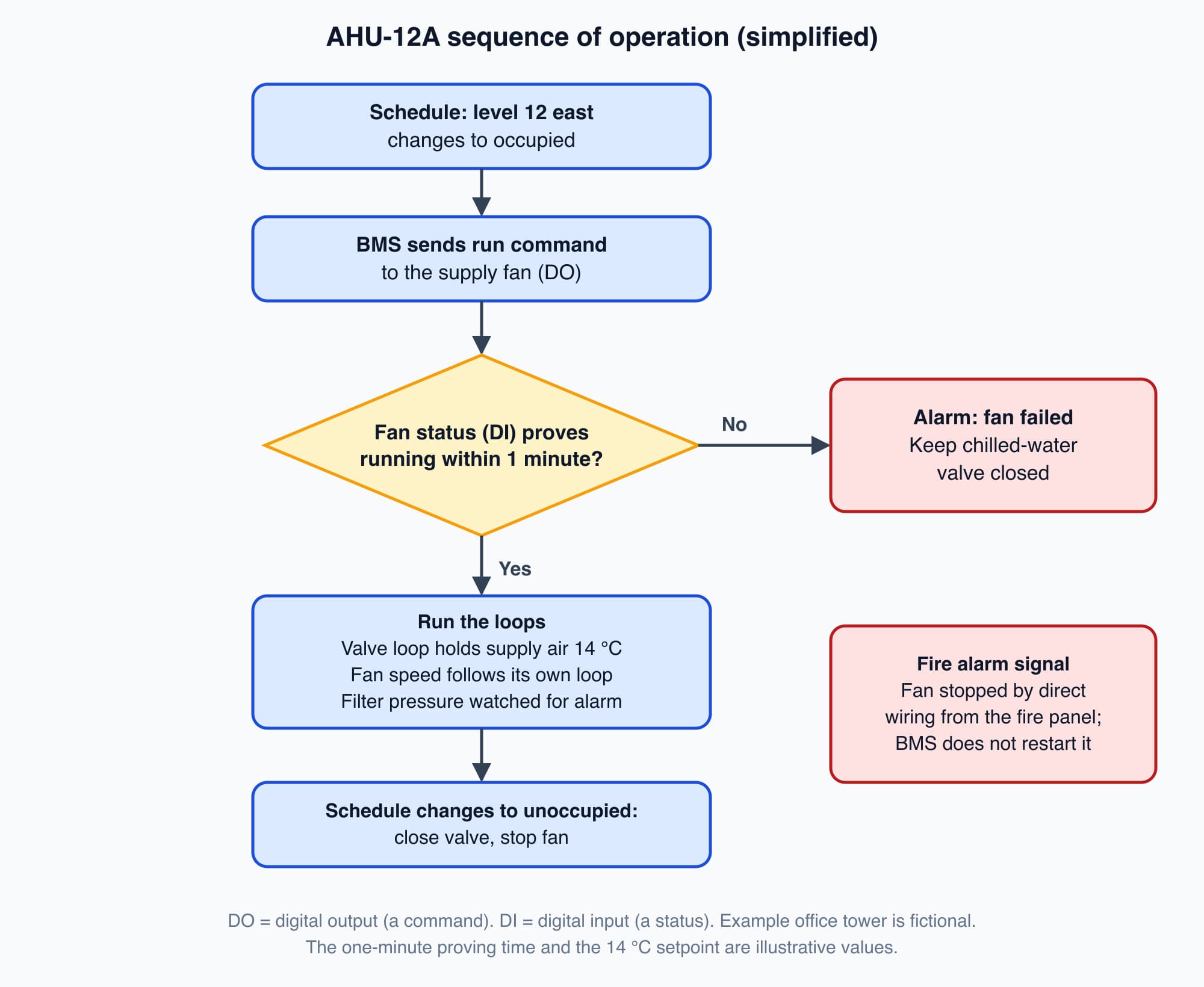
AHU-12A's sequence as a flow chart: the valve loop only runs once the fan status proves the fan is running.
Interlocks wait for proof, not for the command
The "Prove" step said "wait for the fan status". This is the most important habit in a sequence. An interlock is a rule that allows or blocks an action depending on the proven state of other equipment. It does not trust that a command was obeyed. It waits for evidence.
The run command is what the BMS asks for. The status is a separate signal that comes back from the equipment, and what it can prove depends on where it comes from:
- A run contact in the fan's drive or starter only proves that the drive or starter has switched on. The motor could be turning with a broken belt and moving no air, and this contact would still say "running".
- A differential pressure switch across the fan closes only when the fan is building up air pressure, so it proves that air is moving.
- A current switch on the motor cable is set to see the motor's normal working current. A motor turning a broken belt draws much less, so the switch drops out.
For AHU-12A, the fan status should come from a differential pressure switch or a current switch, so that it proves airflow and not just a closed starter. With that in place, if the command says "run" and the status still says "stopped" after the set delay, something is wrong: the drive may have tripped, the fan belt may have broken, or someone may have switched the fan off at the panel. A good sequence never treats "commanded" as "running". Part 15 checks where the status signal really comes from before the building is handed over.
The chiller plant in the office tower has the classic interlock. A chiller takes heat out of the chilled water that cools the building and passes that heat into a second water loop, the condenser water loop. The condenser water carries the heat up to the cooling towers on the roof, which release it to the outside air. (How a chilled water system works and how a cooling tower works in the Cooling Fundamentals course explain these loops. For this part you only need the direction of the heat: from the building, through the chiller, to the tower.)
The moment a chiller starts, it begins pushing heat into the condenser water. If that water is not already flowing and the tower is not ready to release heat, the pressure and temperature on the condenser side rise within seconds. The chiller then trips on its high-pressure safety, or, if a safety fails, it can be damaged. So the sequence enforces an order:
- Start the condenser water pump and prove that water is flowing. A flow switch or a pressure reading confirms it. A running pump motor is not proof that water is moving.
- Enable the cooling tower fan so the tower can release heat. (In practice the tower fan often starts or speeds up as the condenser water warms.)
- Only then allow the chiller to start.
(A chiller also needs proven flow in its chilled water loop before it starts. We focus on the condenser side here because it shows the order most clearly.)
On shutdown the order reverses. When the chiller stops, the condenser water pump and tower keep running for a set time, because the chiller still holds hot refrigerant that needs to give up its heat. The sequence then stops them.
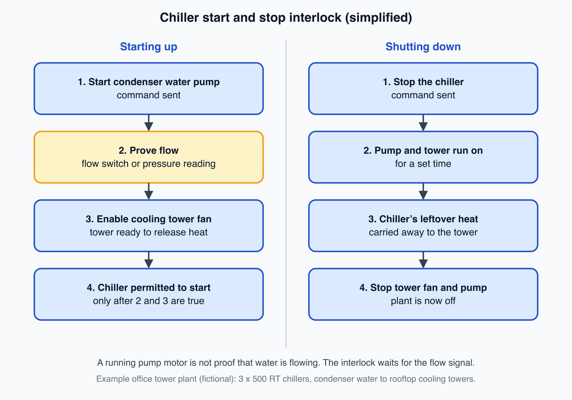
The chiller is only allowed to start after the condenser water flow is proven. On shutdown, the pump and tower run on for a set time.
Some interlocks are kept outside the BMS altogether. In most buildings, the fire alarm panel is wired directly to trip fans such as AHU-12A, so the trip works even if the BMS is switched off. The BMS reads the fire alarm signal so it can show and record what happened, and so its own sequence does not try to restart the fan.
A good sequence says what happens when something fails
Every sequence should state what happens when a part fails, because that is when people most need predictable behaviour. For AHU-12A, the sequence might say:
- The fan does not prove. Raise an alarm and keep the chilled water valve closed.
- The supply air sensor fails. If the reading disappears or goes outside a believable range, raise an alarm and hold the valve at a fixed position written in the sequence, so the floor gets some cooling until the sensor is repaired.
- The supply air stays too warm. If the supply air stays well above 14 °C for a set time even with the valve fully open, raise a "failure to achieve setpoint" alarm. The loop is doing all it can, so the cause is elsewhere, perhaps in the chilled water supply. Part 8 shows how to read this on a trend.
- The network fails. AHU-12A's controller keeps running its own sequence with its own schedule and setpoints, as Part 3 explained. The operator loses the view, not the control.
- The power fails and returns. The controller restarts the fan on its own after a set delay. The delay is chosen so that dozens of AHUs do not all start at the same moment. Part 14 explains why that matters for the electricity bill.
- The fire alarm operates. The fan stops through the direct wiring, and the sequence does not restart it until the fire alarm is reset.
Staging brings plant on and off one machine at a time
A building's cooling load changes through the day. A Malaysian office is nearly empty at 7am, full and sunlit by 2pm and emptying by 7pm. One chiller large enough for the 2pm peak would spend most of the day running at a small fraction of its capacity, and chillers, like most machines, run less efficiently when badly under-loaded.
So larger plants use staging: several machines, brought on one at a time as the load rises and turned off as it falls. The office tower has three 500 RT chillers (RT, refrigeration tons, measure cooling capacity), with two on duty and one on standby. Its sequence says, in outline, to start the next chiller (with its own pump and tower interlock) when the running ones cannot hold the chilled water setpoint for a set time, and to stop one when they are lightly loaded for a set time. Staging also gives resilience: if one chiller trips, the standby machine can start. Part 12 covers chiller staging in detail.
Modes let the same reading lead to different actions
A building behaves differently at 3am than at midday. A sequence handles this with modes, which are named states that each have their own rules. The main ones for AHU-12A are:
- Occupied: the floor is in use, and the loops hold their normal setpoints.
- Unoccupied: the floor is empty, and the cooling is relaxed or off.
- Start-up (pre-cooling): the period before occupancy when the plant brings the floor to comfort.
- Fire: the fan is stopped and stays stopped until the fire alarm is reset.
Modes matter because the same reading can mean different things. A floor at 26 °C needs action in occupied mode but may be fine in unoccupied mode. With modes, the sequence states the rules once for each mode, and the schedule switches between them. How far the setpoint is relaxed at night, and how the BMS decides when to start pre-cooling, are covered in Part 7.
In the office tower, the BMS also runs the lighting schedules and the car park ventilation fans. Their sequences are usually simpler, often a schedule plus one or two conditions. Fire systems have their own control panels and rules, and the BMS mostly monitors them.
The adjustable numbers are what commissioning tunes
Inside every sequence are numbers that are meant to be adjusted, because no design is perfect on paper and every building behaves a little differently once it is built:
- Setpoints are the targets, such as 14 °C supply air or a chilled water supply temperature.
- Time delays are the waits written into the rules: how long a condition must last before staging up, how long the condenser pump runs on after a chiller stops, how long a value must be out of range before an alarm is raised. Delays stop the plant reacting to every brief wobble.
- Deadbands are the gaps between an "on" point and an "off" point, used for switching, staging and alarms, as Part 4 explained. For example, a stage-up threshold and a lower stage-down threshold stop a chiller being switched on and off repeatedly.
- Tuning settings are the gain and integral settings of each modulating loop, from Part 5.
Setting these numbers well is most of what commissioning (proving the system works before handover) and later optimisation involve. Stage up too eagerly and you run machines you did not need. Stage up too slowly and the building overheats before help arrives.
Timing also affects the electricity bill. On a tariff with a maximum demand charge, such as the office tower's Medium Voltage (MV) General tariff, the sequence can avoid starting several large machines at the same time. Part 14 explains how this works. Published savings from better sequences vary widely and depend on the site, so treat any single percentage with caution.
The sequence is the contract, and the start of the test list
A sequence of operation is effectively the contract between the building owner and the automation contractor. The contractor is paid to make the building behave as the sequence describes. If every mode, interlock, failure response, setpoint and delay is written down, both sides know when the job is finished. If the sequence says only "the chillers shall stage as required", there is no agreed meaning for "as required", and every later disagreement has nothing to settle it. Writing and implementing a clear sequence is a core part of building automation work.
A clear sequence also gives you the list of things to test. Each rule becomes a check that someone can witness before the building is handed over. For AHU-12A, the list starts like this:
The sequence says | How to check it |
|---|---|
The fan starts when the floor becomes occupied | Change the schedule and watch the run command and fan status change |
The valve loop holds supply air at 14 °C | Change the setpoint and check on the trend that the loop settles (Part 5) |
If the fan does not prove, raise an alarm and keep the valve closed | Stop the fan at its drive while it is commanded on; the alarm should appear and the valve should stay closed |
The fan status proves airflow, not just a closed starter | Check that the status comes from the differential pressure switch or current switch, not from a contact in the drive or starter |
If the supply air sensor fails, raise an alarm and hold the valve at its fixed position | Disconnect the sensor; check the alarm and the valve position |
The fire alarm signal stops the fan | Simulate the signal together with the fire alarm contractor |
After a power failure, the fan restarts on its own after a delay | Switch the controller's power off and on and time the restart |
Part 15 turns this list into a full commissioning and handover exercise.
Worth knowing: The sequence outlives the project. Years later, when the equipment does something surprising, everyone goes back to the written sequence to answer one question: is the equipment doing the wrong thing, or the thing it was told to do? Keep the final version with the building's records.
What comes next: scheduling and optimum start
AHU-12A's sequence began with "when the schedule changes to occupied". The next part, BMS Scheduling and Optimum Start: How a Building Wakes Itself Up, explains that schedule. It opens with the two questions the section on modes left open: how far can the cooling relax when the floor is empty, and how does the BMS decide when to start pre-cooling?
Check your understanding
- The BMS sends AHU-12A's run command, but one minute later the fan status still says "stopped". What should the sequence do, and why not simply trust the command? It should raise an alarm and keep the chilled water valve closed. A command is only a request. The status, from a differential pressure switch or current switch that sees the fan working, is the evidence. A drive trip, a broken belt or a local switch can all stop the airflow even though the BMS asked the fan to run. (A contact in the drive or starter would not catch the broken belt, because it only proves the starter closed.)
- Why must the condenser water pump be proven before a chiller starts, and why does it keep running after the chiller stops? A running chiller pushes heat into the condenser water straight away. Without proven flow, pressure and temperature on the condenser side rise within seconds and the chiller trips or is damaged. After the chiller stops, it still holds hot refrigerant, so the pump and tower run on for a set time to carry that heat away.
Recap: A sequence of operation is the written "when X, do Y" plan that turns separate loops into equipment that works as one system. It sets the order of starting and stopping, uses interlocks that wait for proven status rather than trusting a command, and says what happens when a fan, sensor, network or power supply fails. It stages chillers on and off, switches between modes, and lists the setpoints, delays, deadbands and tuning settings that commissioning adjusts. Written clearly, it is the contract between owner and contractor and the start of the commissioning test list.
Go deeper on video (optional)
This video walks through sequences for fan coil units, VAV boxes and car park ventilation. The equipment differs from AHU-12A, but the "when X, do Y" logic is the same. It is optional.
MEP Academy walks through how a BMS defines the sequence in which controls respond, using plain fan-coil, VAV and garage-CO examples any building owner can follow.
This is Part 6 of 16 in Cobler's Building Automation and BMS Fundamentals course. Previous: PID Control Explained Simply: Why a Valve Overshoots, Hunts or Settles. Next: BMS Scheduling and Optimum Start: How a Building Wakes Itself Up.
Cobler builds CobiNeural, a platform that shows a facility team its building's energy, water and indoor air data as live numbers across the whole site. To see how your building performs, talk to us.
FAQ
Frequently asked questions
Ask us about this topic
Something in this article you want to dig into — or a situation in your own building it doesn't quite cover? Send us your question. We don't run public comments; the team replies to you directly by email.