Blog
Star vs Delta: Two Ways to Wire Three-Phase
You have three windings and three or four wires, so how do you join them? Star and delta are the only two answers, and they explain the tiny diagram on every motor nameplate.
 Tan Kok XinElectricity Fundamentals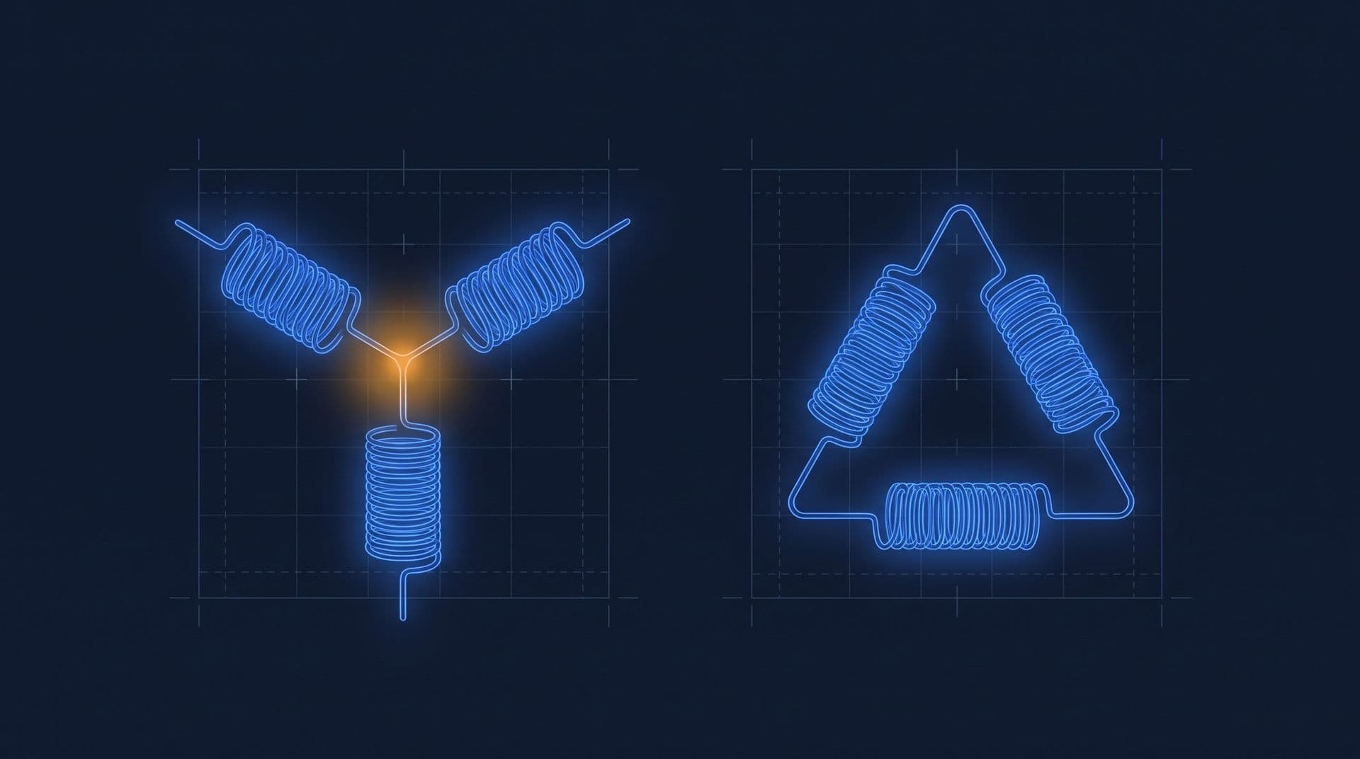
An applied extra to Cobler's Electricity Fundamentals course.
Open the terminal box on the side of any three-phase motor and you find six brass posts in two neat rows, with short metal bars linking some of them together. Look up at the nameplate and there is a tiny drawing next to the voltage rating: a little Y shape and a little triangle, the symbols for star and delta, sometimes with arrows between them. Most people wire the motor the way the electrician did last time and never give that diagram a second thought. But it is telling you something exact. You have three windings inside that frame and three or four wires coming in, and there are only two ways to join them. That choice of star versus delta is what the drawing records, and once you can read it, the six posts stop being a mystery.
Three windings, three wires: how many ways can you join them?
Two. That is the whole answer, and it is smaller than it sounds.
A three-phase machine, whether it is the transformer feeding your building or the induction motor driving your chiller, is built from three separate windings, one per phase. Each winding has two ends. The question of how to connect three windings with two ends each into a three-phase supply has exactly two sensible answers, and electrical engineering has used both for over a century.
You can tie one end of all three windings together at a single common point, and take your three supply lines from the other three ends. That is star, drawn as a Y because three spokes meet at a hub. Or you can chain the windings nose to tail in a closed triangle and take a line from each of the three corners. That is delta, drawn as the triangle. There is no third option that balances, which is why every three-phase device on Earth is one of these two.
What does star connection do to the voltage?
It splits the line voltage between two windings, so each winding sees less than the full line voltage, and it gives you a neutral for free.
In star, the common point where the three winding ends meet becomes the neutral. Now trace the voltage. Each winding runs from that neutral point out to one line, so each winding sits at the phase-to-neutral voltage, which on the Malaysian low-voltage system is 230 V. But the supply lines are taken from the far ends, so the voltage between any two lines spans two windings that peak 120 degrees apart in time. Because they do not peak together, their voltages do not simply add to 460. The three-phase geometry works out to a factor of the square root of three:
$$V_{line} = \sqrt{3} \times V_{phase} = 1.732 \times 230 \approx 400\ V$$
So a star connection quietly does two useful things at once. The windings each handle only 230 V while the terminals present 400 V to the outside world, and the star point hands you a fourth wire, the neutral, that single-phase loads can hang off. That neutral is not a trivial by-product. It is where your whole installation's earth reference is born, which is exactly why the next sibling in this series, on neutral to earth bonding, starts at the transformer's star point.
What does delta connection do differently?
It puts the full line voltage across every winding and refuses to give you a neutral at all.
In delta each winding is wired directly between two lines, corner to corner of the triangle. There is no common point, so there is no neutral to bring out. And because each winding now bridges two lines directly, it sees the whole 400 V, not 230. The current relationship flips: the line current splits between two windings at each corner, so the line carries the square root of three times what any single winding carries. Star trades voltage down and keeps current whole; delta keeps voltage whole and trades current up. They are mirror images of the same geometry.
The practical consequence is blunt. Delta gives you the most winding voltage and no neutral. Star gives you a neutral and gentler winding voltage. That single difference decides where each one is used.
Star vs delta: where each connection actually lives
Star lives on the transformer that feeds your building. Delta lives inside a great many of the motors that building runs.
The distribution transformer that steps grid voltage down to the 400/230 V at your intake is almost always wired with a star secondary, precisely because that arrangement produces a neutral point. Without it there would be no neutral wire, and every single-phase load in the building, every light and socket and small appliance, would have nothing to connect its return to. The star point of that transformer is where your neutral and your earth reference both begin.
Motors are a different story. A motor does not need a neutral; it is a balanced three-phase load with nothing single-phase hanging off it. Many industrial motors are therefore designed so that their windings are wound for the line voltage and run in delta, each winding taking the full 400 V it was built for. Whether a specific motor runs in star or delta is set by its nameplate and the supply it is fed, so read the plate rather than assume. But a motor built to run in delta at 400 V is the case behind the neatest trick in this whole article.
The payoff: why a motor starts in star and runs in delta
Because the two connections are a built-in two-speed gearbox for starting, and you already own both.
Recall the problem from the motors article: throw a large motor straight onto the line and it gulps six to eight times its running current for a couple of seconds, dragging the whole switchboard's voltage down and dimming every light on the feeder. A star-delta starter solves this with nothing more exotic than the two ways of joining the same three windings.
Wire the motor in star to start it. Now each winding sees only its phase voltage, \(400 / \sqrt{3} \approx 231\ V\), which is about 58% of the 400 V it would get in delta. Torque follows the square of voltage, so \((1/\sqrt{3})^2 = 1/3\): the motor produces roughly one-third of the torque it would make in delta. The current drawn from the supply also settles at about one-third, but by a different route. Current is linear in voltage, so each winding at 58% of its delta voltage pulls about 58% of its delta winding current. On top of that, delta's line current is the square root of three times its winding current while star's line current is simply the winding current, so switching to star divides the supply current by a further factor of the square root of three. The two reductions compound to one-third. It spins up gently, the lights barely flicker, and then, once it is near full speed, a timer switches the contactors over to delta. Each winding now gets its full 400 V, full torque is available, and the motor runs normally.
The catch is that one-third of the torque is all you get during the star phase, so star-delta starting only suits loads that start unloaded or lightly loaded, such as pumps, fans and off-load compressors. Ask it to start against a heavy load and the motor simply stalls in star, never reaching the speed where the changeover makes sense. There is also a brief open-transition gap during the switch, tens of milliseconds where the still-spinning motor is momentarily disconnected, and reclosing out of step can throw a current spike back toward direct-on-line levels (closed-transition starters add a contactor to bridge it). It is the cheapest reduced-voltage start there is, which is why it endures despite these limits, with a soft starter or VFD taking over when the load needs more control.
Reading the nameplate and the six terminal posts
Now the six brass posts make sense. The three windings are brought out to six terminals, conventionally labelled U1, V1, W1 for one end of each winding and U2, V2, W2 for the other. The short linking bars are how you choose the connection. Bridge the three "2" ends together and feed the supply into U1, V1, W1, and you have made a star: the bridged bar is the star point. Rearrange the bars so each winding's end links to the next winding's start, and you have closed the triangle into delta. A star-delta starter is just a set of contactors that make those two link patterns in turn, first one, then the other.
That little Y-and-triangle drawing on the nameplate is the wiring instruction for exactly this. It shows which posts to bridge for each connection and the voltage the motor expects in each. It was never decoration. It is the same square root of three you now carry from the three-phase article, stamped in metal on the side of every motor in the plant.
Go deeper on video
Reading explains; watching sometimes lands the picture. Full credit to the creators:
"Star and Delta Connection Explained" by TheElectricalGuy
"Delta and Wye: Volts, Amps and VA" by Dave Gordon
This is an applied extra to Cobler's Electricity Fundamentals course. It picks up where Three-Phase Power Explained and How Electric Motors Work leave off, and its neutral point leads straight into neutral to earth bonding.
Those star-delta starts and the motors behind them are where a lot of your peak demand and power-factor cost is made. See what CobiNeural monitors on every motor you run, or book a demo to see your own load.
FAQ
Frequently asked questions
Ask us about this topic
Something in this article you want to dig into — or a situation in your own building it doesn't quite cover? Send us your question. We don't run public comments; the team replies to you directly by email.