Blog
Adding in Binary: the Adder and the ALU
Can gates do sums? Part 3 builds a binary adder from an XOR and an AND, adds 5 + 3 with the carry rippling across four full adders, subtracts by adding the negative, and compares two numbers by reading one bit, which is how a building controller asks whether CO2 is below 600 ppm.
 Tan Kok XinHow a Computer Works

Part 3 of 13 in Cobler's How a Computer Works course. New here? Start with the course map.
Part 2 left us with gates that can make any yes-or-no decision, and a question. Can they do sums? Well, here's something that might sound backwards at first. In our office tower's level 9 air handling unit (AHU) controller, a chip asks about once a second (illustrative) whether the meeting room's CO2 is below 600 ppm, and it answers that question with a binary adder, the same circuit it uses for sums. So let's see how gates add, and then how adding can answer a question like that.
Adding in columns
Let's start with a sum on paper, the way we learned at school. To add 58 and 37, we start on the right. 8 + 7 is 15, so we write 5 and carry 1 into the tens column. Then 5 + 3, plus the carry, is 9. So we get 95. Notice that every column does the same small job. It adds two digits and a carry, writes one digit, and passes one carry on.
Binary works exactly the same way, except each column only ever holds a 0 or a 1, so there are just four cases. We can make a little table, where the carry is what spills into the next column:
A | B | Sum | Carry |
|---|---|---|---|
0 | 0 | 0 | 0 |
0 | 1 | 1 | 0 |
1 | 0 | 1 | 0 |
1 | 1 | 0 | 1 |
The last row is the only interesting one. 1 + 1 is two, and two in binary is 10, so we write 0 and carry 1, just like 8 + 7 made us carry in decimal.
The half adder
Now look at the carry column. It's 1 only when A and B are both 1, which is exactly the AND gate from Part 2. And the sum column is 1 when one input is on but not both. That's a close cousin of OR, and we call it XOR, short for exclusive OR. We can build it from gates we already have, as (A OR B) AND NOT (A AND B), or from four NAND gates. So an XOR and an AND side by side add one column of binary, and we call that pair a half adder.
The full adder
Why only half? Because it adds just two bits, and every column except the first also has a carry coming in from its right. So we give it a third input, the carry in. Three bits can add up to 0, 1, 2 or 3, which in binary is 00, 01, 10 or 11, so there's still just one sum bit and one carry bit coming out. Two XORs make the sum, and two ANDs and an OR make the carry. That's what we call a full adder, and a common way of building one in CMOS takes 28 transistors.
Let's check the busiest case, 1 + 1 with a carry of 1 coming in. That's three, which is 11 in binary, so the sum is 1 and the carry out is 1.
The binary adder
Now let's line up four full adders, one for each column, with each one's carry out feeding the carry in of the one on its left. Let's add 5 + 3. In four bits, 5 is 0101 and 3 is 0011.
- Right-hand column: 1 + 1 is two, so we write 0 and carry 1.
- Next column: 0 + 1, plus the carry, is two again, so 0, carry 1.
- Next: 1 + 0, plus the carry, is two, so 0, carry 1.
- Last: 0 + 0, plus the carry, is 1.
So we get 1000, which is 8. Four full adders in a row did exactly what we do on paper, and that's a binary adder. The carry ripples from right to left like a row of dominoes falling, so we call this design a ripple-carry adder. Each column has to wait for the carry from the one before it to arrive, and that little wait is going to matter in Part 4.
For bigger numbers we just add more columns. Twelve full adders add two 12-bit numbers, and at 28 transistors each that's 12 × 28 = 336 transistors. Imagine building that out of relays. On a chip, it's a speck too small to see.
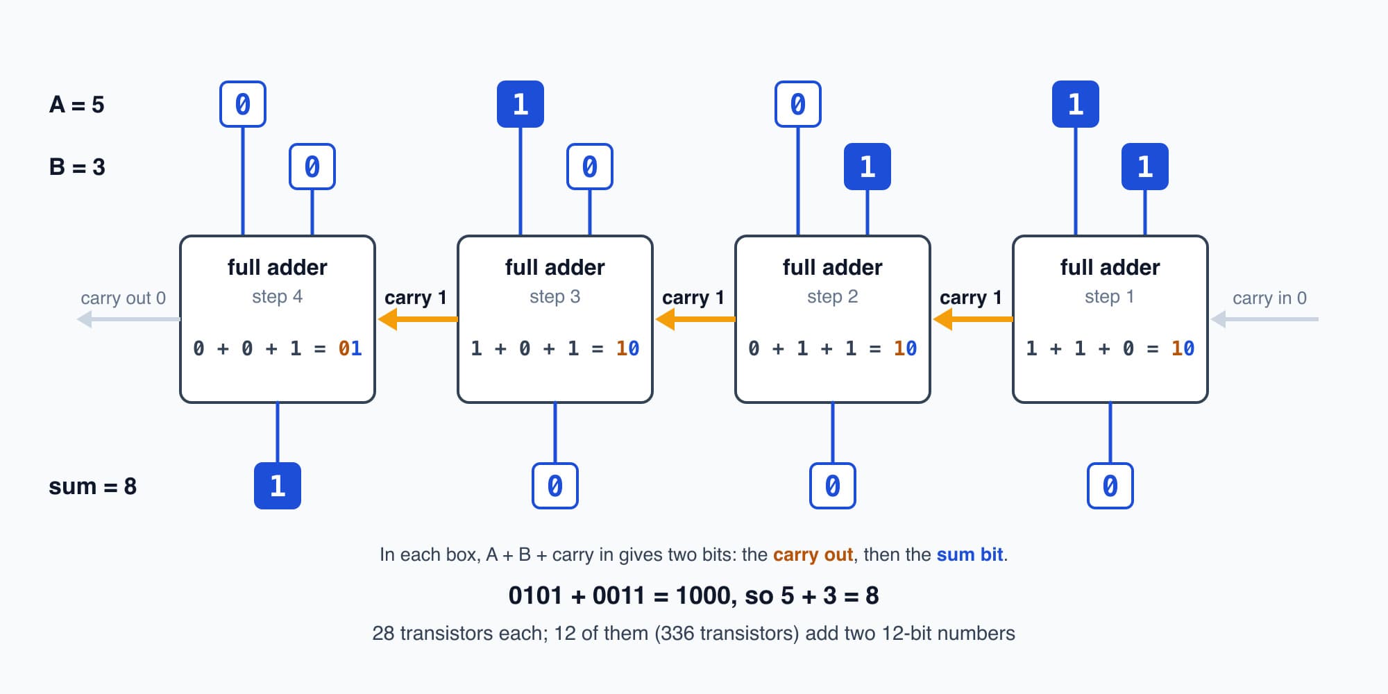
Each column adds two bits and a carry, then passes its own carry left, so the carry ripples across the row like falling dominoes.
Try it. Add 9 + 8 on four full adders. What do the four outputs show, and where did the rest of the answer go?
Show the worked answer
9 is 1001 and 8 is 1000. In the right-hand column, 1 + 0 = 1. The next two columns are 0 + 0 = 0. In the last column, 1 + 1 is two, so 0, carry 1. So the outputs show 0001, which is 1, and the carry out of the last column is 1.
That carry is worth 16, and 16 + 1 = 17, which is the right answer. But with only four columns, it has nowhere to go. That's called an overflow, and real chips keep that last carry in a spare bit so the program can tell it happened.
Subtraction
So the adder adds. What about taking away? You'd think we'd need a second circuit that borrows the way we do on paper. But there's a neater trick, and it goes back to the odometer from Part 1.
Picture our binary odometer showing 0000, and roll it back by one. Every wheel rolls back past 0 to 1, so it shows 1111. So on a four-wheel odometer, 1111 behaves just like −1. Roll back once more and it shows 1110, which is −2, and so on. If we agree that a 1 on the left-hand wheel, which we call the top bit, means a negative number, four bits can hold everything from −8 to 7. That way of writing negative numbers is called two's complement.
And there's a simple rule for making any negative number. Flip every bit, then add 1. For −3, we flip 0011 to get 1100, then add 1 to get 1101.
Now we can subtract by adding, because 5 − 3 is the same as 5 + (−3):
$$0101 + 1101 = 1\,0010$$
The fifth bit at the front is the last carry, and with only four columns it falls off the end, so we're left with 0010, which is 2. And we don't need a new circuit for any of it. The flipping is a row of NOT gates in front of the adder's second input, and the "add 1" is just the first column's carry in, set to 1 instead of 0.
Comparing
Let's try it the other way round, 3 − 5. For −5 we flip 0101 to get 1010 and add 1 to get 1011. Then 0011 + 1011 = 1110. The top bit is 1, so the result is negative, and 1110 is −2, which is right.
That top bit is the useful part. If all we want to know is whether one number is smaller than another, we can subtract and look at the top bit, and ignore the rest. Is 3 below 5? 3 − 5 has a top bit of 1, so yes. Is 5 below 3? 5 − 3 = 0010 has a top bit of 0, so no. So a comparison is one subtraction and one bit, and chips set that bit aside as what's called a flag. We'll need it in Part 5. (If the numbers are big enough to overflow, the top bit on its own can mislead, so real chips check the carries too. Our numbers will always fit.)
The ALU
So now we've got an adder, a subtractor that's really the same adder, and a comparison that's a subtraction with one bit kept. From Part 2 we've also got plain gates, which can AND or OR two whole numbers bit by bit. But how can one circuit do whichever of those jobs we want?
Well, what if we build them all side by side, feed the same two numbers into every one, and then pick just one answer to let through? The picker is called a multiplexer, but let's just call it a chooser. A chooser between two answers needs one control bit, which we'll call s, and it's only gates again. It lets through (first answer AND NOT s) OR (second answer AND s), so with s at 0 the first answer gets through, and with s at 1 the second one does. Two control bits can choose between four answers.
That whole block, the adder and its relatives with a chooser on the end, is what we call the ALU, the arithmetic logic unit, and its control bits are the chooser bits. Each real chip has its own codes, so in this course we'll use one simple set. 00 adds, 01 subtracts, and 10 compares, keeping only the top bit. That leaves 11 for a fourth job, and the toy computer in Part 5 uses it for dividing.
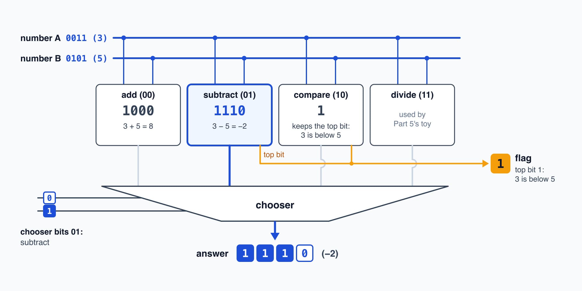
Every job works on the same two numbers at once, and two chooser bits, in this course's own codes, pick which answer gets through.
Try it. Set the chooser to 01, subtract, and work out 7 − 2 in four bits. Then set it to 10, compare. Is 7 below 2?
Show the worked answer
For −2, flip 0010 to get 1101, then add 1 to get 1110. Then 0111 + 1110 = 1 0101, and the fifth bit falls off, which leaves 0101, or 5.
For the compare, the ALU does the same subtraction and keeps only the top bit, which is 0. So no, 7 isn't below 2.
Sums and comparisons everywhere
You'd think a computer must have some cleverer maths hidden away somewhere. But this is basically all the arithmetic it has. Every sum and every comparison, from 2 + 2 to deciding whether your tap landed on a button, goes through an ALU like this one.
Multiplying, for example, is adding shifted copies. Shifting a binary number one place to the left doubles it, the same way shifting a decimal number one place left multiplies it by ten. So let's take CWP-2's night, 27 kW for 4 hours. 27 is 0001 1011, and shifting it two places left gives 0110 1100, which is 64 + 32 + 8 + 4 = 108. That's the 108 kWh CWP-2 used for nothing that night, worked out just by moving bits along. Dividing can be done by subtracting over and over. And whether a tap landed on a button turns out to be four subtractions and their top bits, which we'll work through in Part 8.
The level 9 AHU controller
So let's go back to the question from the start. It's 10 a.m. on the same Monday, and a meeting in the level 9 room has pushed the CO2 up to 1,000 ppm. The AHU controller holds the reading as a number, and each time round its program it works out the reading minus 600 on its adder. Twelve bits are plenty for this, since in two's complement they hold −2,048 to 2,047 and the sensor only reads 0 to 2,000 ppm. So 1,000 − 600 = 400, which in 12 bits is 0001 1001 0000. The top bit is 0, so the CO2 isn't below 600, and the fresh-air damper should be opening.
That afternoon, with the room empty, it reads 450 ppm. Now 450 − 600 = −150, which in 12 bits is 1111 0110 1010. The top bit is 1, so it's below 600, and the damper can go back to 0%.
And the subtraction does double duty. The 400 that came out isn't thrown away, because it's exactly how far past 600 the room is, and that's what the controller needs to work out how far to open the damper. All of it is one pass through twelve full adders, 336 transistors, and it's done within one tick of the controller's clock.
Answers that vanish
But there's a catch. The adder's answer only exists while its inputs are held there. Change the 5 in our 5 + 3 to a 6, and the 8 is gone, replaced by 9 the instant the carries settle, with no trace that it was ever 8. It's the same in the controller. The 400, the 600 it was compared with and the reading itself all vanish the moment anything upstream changes, and gates on their own have no way to keep them. So to use an answer in the next step, we need switches that remember. How do we build those out of gates that forget? That's Part 4: Memory.
This is Part 3 of 13 in Cobler's How a Computer Works course. Previous: Logic Gates. Next: Memory: Latches, Registers and RAM.
Cobler builds CobiNeural, which runs comparisons like these across every meter and sensor in a building and flags the readings that drift from normal. To see it on your own site, request a demo.
FAQ
Frequently asked questions
Ask us about this topic
Something in this article you want to dig into — or a situation in your own building it doesn't quite cover? Send us your question. We don't run public comments; the team replies to you directly by email.