Blog
Building Controllers: PLCs and DDC
Why don't building controllers run Windows? Part 12 opens a controller: a microcontroller, AI, AO, DI and DO points as numbers in memory, the scan cycle on a fixed beat, ladder logic drawn like relays, the watchdog that puts outputs safe, and the pumps it runs.
 Tan Kok XinHow a Computer Works
Part 12 of 13 in Cobler's How a Computer Works course. New here? Start with the course map.
Imagine the computer running the tower's condenser water pumps stopped for a few minutes to install updates, or greyed out with "Not responding" like the stuck app in Part 6. On a laptop that's an annoyance. In a chiller plant, a pump that stops while its chiller is running can trip the chiller, and a pump that never stops wastes power all night.
Part 11 finished the laptop and ended on the tower's other computers, the ones asked to run a pump safely every second for ten years. So what's different inside them, and how does a PLC work? A PLC, or programmable logic controller, is one of the computers that run plant like this, and the best way to see what makes it different from a laptop is to open one up.
The microcontroller
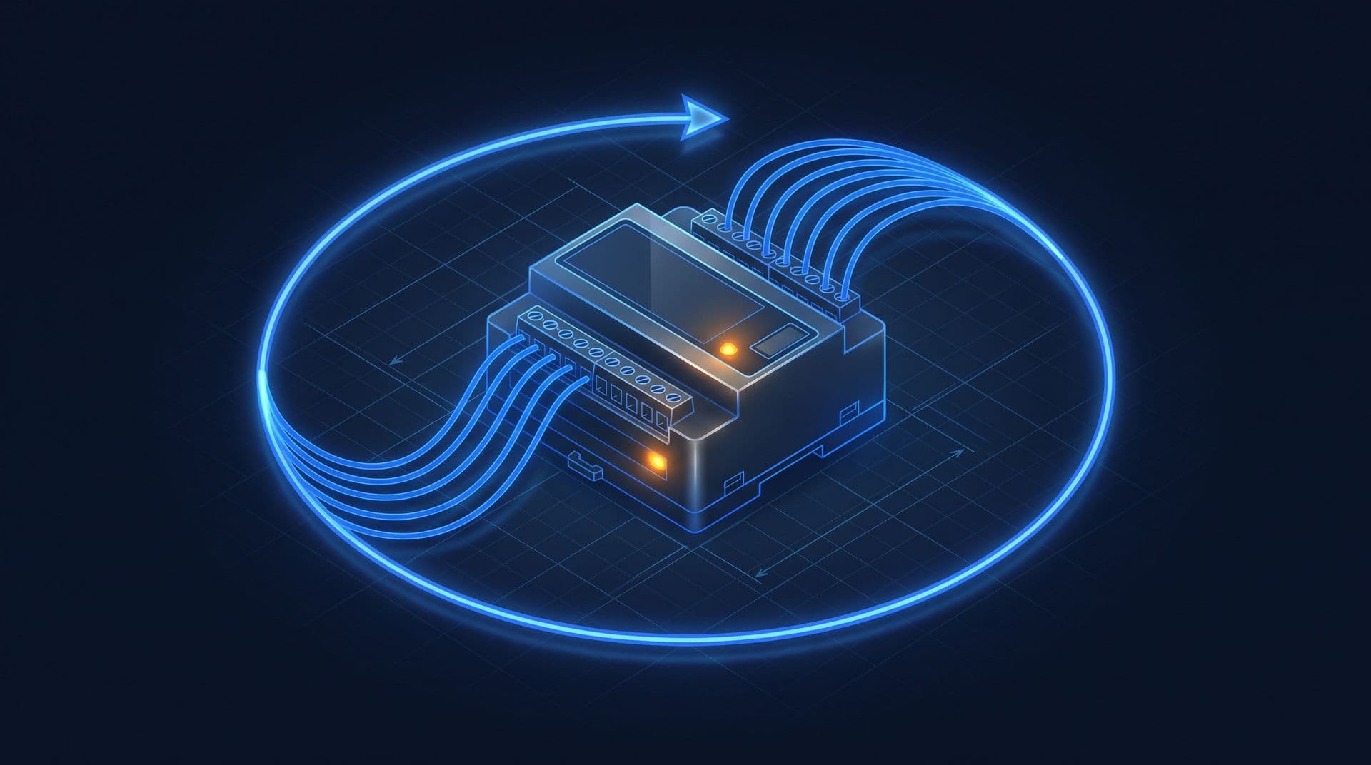
Take the cover off a building controller and we find the pieces from this course on one circuit board, and often on one chip. There's a processor that fetches, decodes and executes (Part 5), flash memory holding the program (Part 9), RAM for the numbers it's working on (Part 4), and pins that connect to the outside world. A chip with all of that on it is the microcontroller we met inside the level 9 AHU controller in Part 5. It's far smaller and slower than a laptop's processor, with no screen at all, and for running one plant it doesn't need any more.
I/O points
Those pins lead out to the controller's terminals, and every wire on those terminals is one of the four point types from Electricity Part 20:
- Analog input (AI): a reading on a range, like a CO2 sensor's 4 to 20 mA. An analog-to-digital converter (ADC) turns it into a count, so 12 mA (1,000 ppm) becomes 2,458.
- Analog output (AO): a number turned back into a voltage, usually 0 to 10 V, which sets a damper's position or a drive's speed.
- Digital input (DI): a contact that's open or closed, like a pump's running status or a flow switch.
- Digital output (DO): one bit that energises a relay coil, which starts a pump or a fan.
Now this is where Act 2 comes back. To the controller's program, every one of those points is a number at an address, just like slots 14 and 15 in Part 5's toy, or the mouse and the screen to the laptop. The count from analog input 1 sits at one spot in memory. Writing a 1 at another spot closes the relay on digital output 3.
How a PLC works
So how does the program use them? A laptop runs whatever's busy, in time slices, whenever the operating system decides. A controller does something much simpler. It goes round one loop, the same way every time:
- Read every input, and copy its value into a block of memory called the input image.
- Run the whole program from top to bottom, using only those copied values, and put the results in another block, the output image.
- Copy the output image out to the terminals.
- Do the housekeeping, like answering the building management system (BMS) over the network.
Then it goes back to step 1. Each trip round that loop is what we call a scan, and the time it takes is the scan time.
Why copy the inputs first? Because then the program sees one frozen moment. If a flow switch flicked halfway through, part of the program would see "flow" and part "no flow", and it could make a decision that's half of each. With the copy, every line of the program agrees about the world for that scan.
Many controllers also run the loop on a fixed beat. If the program only needs 20 ms but the scan is set to once a second, the controller waits out the rest of the second and starts again on time. For an air handling unit (AHU) sequence, about once a second is common, and a fast task in a PLC might run every 10 ms (both illustrative). Even the controllers that loop as fast as they can do the same steps every time, so their scan time hardly changes. So we know the longest the controller can take to react to any input, and that's what makes it predictable in a way a laptop isn't.
Let's compare. In Part 6 the laptop switched programs about every 4 ms. If 20 busy programs shared one core, a full round of turns would take 20 × 4 = 80 ms, and much longer if the drive is busy or an update starts (illustrative). Most of the time that's fine, but nobody can say in advance how long the worst wait will be.
Ladder logic
So what does the program look like? Many PLCs are still programmed in ladder logic, which looks just like a drawing of the relay circuits from Part 2. Each rung of the ladder runs from left to right, with contacts on the left (inputs, or bits in memory) and a coil on the right (an output). Contacts in series make AND, contacts side by side make OR, and a contact drawn with a slash through it is normally closed, so it's NOT.
There's a good reason for the look. The first PLCs came out at the end of the 1960s to replace walls of relays in car plants, and drawing the program as relays meant the electricians who looked after those plants could read it without learning to code.
Let's write the pump interlock as one rung:
`--[ CWP-1 start ]--[/ CWP-2 running ]--( CWP-1 run )--`
Reading it left to right, CWP-1 runs if its start command is on AND CWP-2 is NOT running. On every scan the controller works the rung out from the copied inputs, which is just the ALU from Part 3 doing AND and NOT on two bits in memory. Building controllers more often use function blocks instead, boxes for jobs like "temperature loop" or "schedule" wired together on a screen, but underneath they turn into the same kind of instructions.
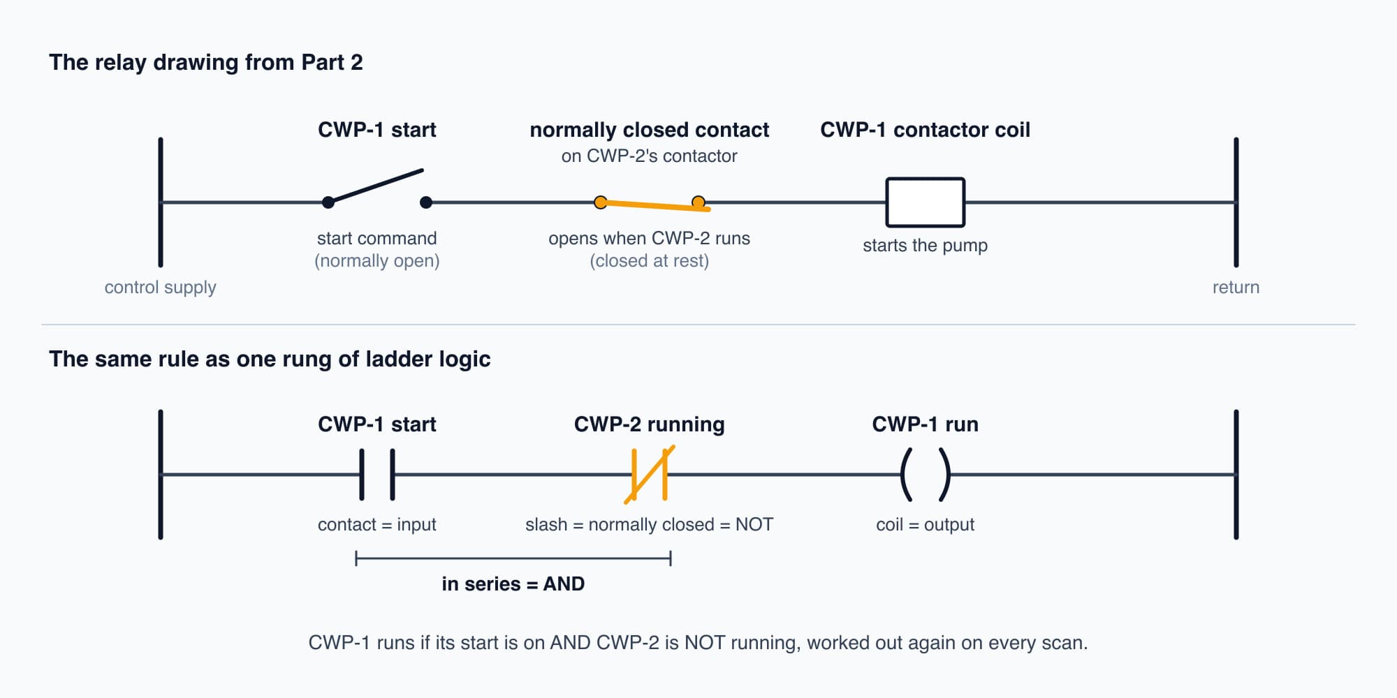
Ladder logic is the relay drawing, run by the processor on every scan.
Try it. Write the matching rung for CWP-2.
Show the worked answer
It's the mirror image:
`--[ CWP-2 start ]--[/ CWP-1 running ]--( CWP-2 run )--`
CWP-2 runs only if its own start command is on AND CWP-1 is NOT running. Together the two rungs mean that whichever pump is already running blocks the other, so the program can never start both.
The watchdog
Now, what if the program itself goes wrong? Say a bug makes it loop forever somewhere in step 2. It never reaches step 3, so the outputs freeze wherever they were, and a pump might run on, or a valve might stay shut, with nothing in charge.
So controllers have a watchdog. It's a separate timer circuit that counts down on its own, and the program has to reset it once every scan, which engineers call kicking the watchdog. A healthy program gets round the loop and kicks it in time, over and over. A stuck program never comes back to kick it, so the timer runs out and the watchdog takes over. On most controllers it stops the program, drives the outputs to a safe state that was set in advance (usually off), and raises a fault. Then, depending on the controller, it either restarts the program or waits for someone to check it.
Say the scan should take 1 second and the watchdog is set to 3 seconds (illustrative). One slow scan is tolerated. But three seconds without a kick, and the outputs go safe.
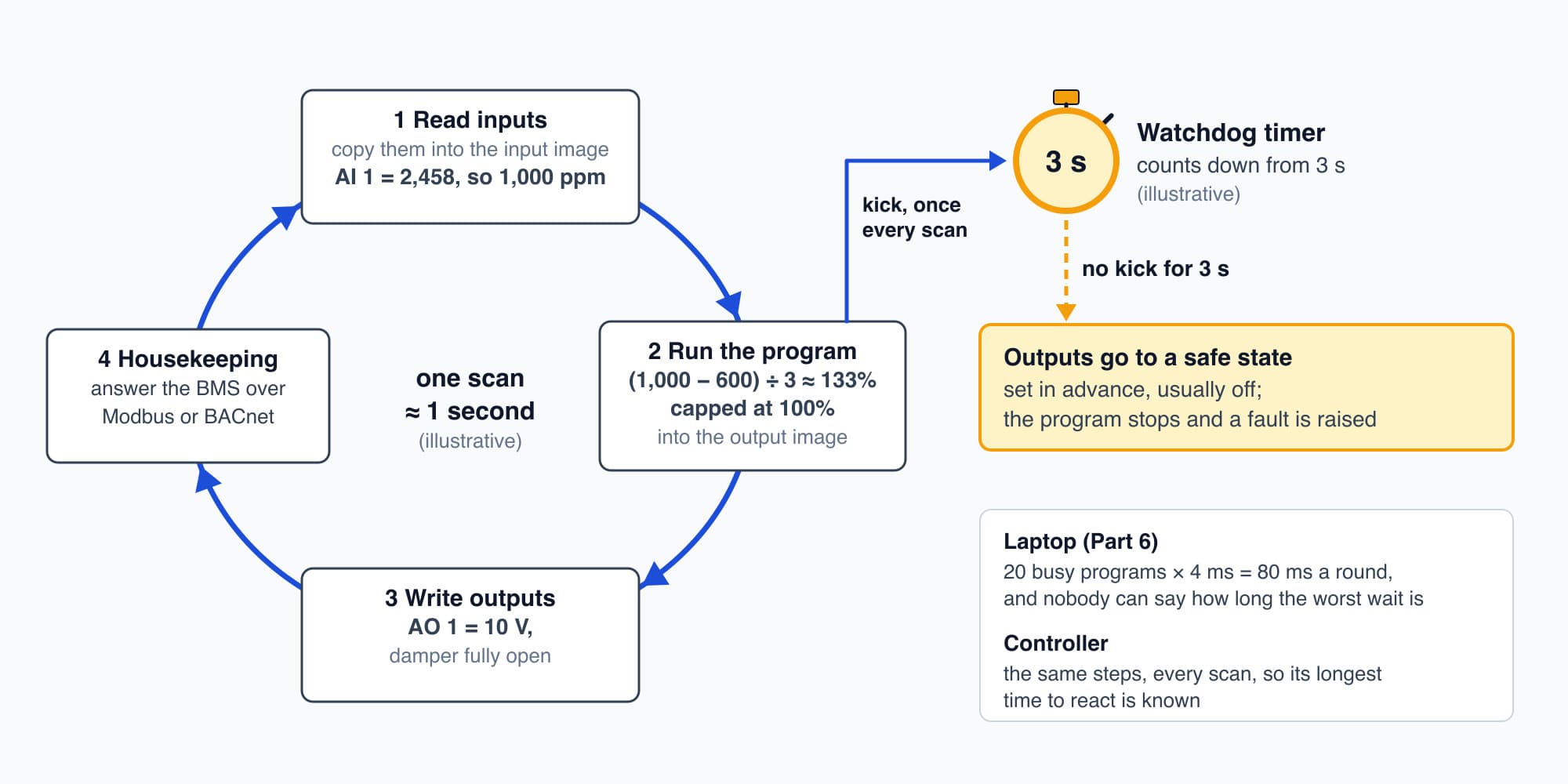
Read, run, write, repeat, on a fixed beat, with a watchdog waiting for every scan's kick.
Try it. The level 9 AHU controller scans once a second, and its watchdog is set to 3 seconds (illustrative). Its last good kick is at 10:00:00, and then the program gets stuck. When do the outputs go safe, and what is the damper doing until then?
Show the worked answer
The watchdog runs out 3 seconds after the last kick, so at 10:00:03. Until then the program never reaches step 3, so no new values reach the terminals, and the damper simply stays where the last good scan put it.
At 10:00:03 the watchdog drives the outputs to their safe states, which for this AHU might be the fan off and the damper at its set fail position, and it raises a fault that the BMS can see on its next poll.
Talking to the building
A controller rarely works alone. In step 4 of each scan it answers questions over its network, so the BMS can read its numbers and send it new setpoints. In buildings the common languages are Modbus (Electricity Part 22) and BACnet, and BACnet vs Modbus compares the two.
PLCs and DDC controllers
So what's the difference between a PLC and the DDC controllers in most buildings? Inside, not much. A PLC came from factories, so it's built for fast, exact sequences, and an engineer usually writes its program from scratch. A direct digital control (DDC) controller came from building air conditioning, so it often arrives with ready-made blocks for temperature loops and schedules, and with BACnet built in. Both are microcontrollers running a scan. In a big tower, the chiller plant might run on a PLC while each AHU gets its own DDC controller. Controllers, DDC and I/O points covers how they're specified.
Why controllers don't run Windows
So why not just run the pumps from a laptop? The scan is one reason, and there are others. A controller has no spinning disk to fail and no updates restarting it at night. Its program is small and fixed, so there's very little to go wrong. It's built to sit in a hot, dusty plant room on 24 V for many years. And when its power blinks, it starts straight from its flash and is back in its scan quickly, while a laptop would still be working through the boot chain from Part 6.
Even so, the copper interlock from Part 2 stays, with each pump's contactor coil wired through a normally closed contact on the other pump's contactor (Electricity Part 6 shows the wiring). However reliable the program is, the safety layer is built so that it doesn't depend on any software at all.
Two controllers in the tower
So let's watch two controllers in our tower. On level 9, the AHU controller scans about once a second (illustrative). When the meeting room fills up, the CO2 sensor's loop reaches 12 mA, which the analog input's ADC turns into a count of 2,458, so 1,000 ppm. In step 2 the program runs the damper rule we stepped through in Part 5, (CO2 − 600) ÷ 3 percent, which starts opening the damper at 600 ppm and has it fully open by 900:
$$\frac{1000 - 600}{3} \approx 133\% \ \Rightarrow \ \text{capped at } 100\%$$
Part 5's toy never went above 900 ppm, so it never needed that cap, but the real controller does. So in step 3 it writes full open, 10 V, to the damper's analog output. One second later it does it all again.
Down in the chiller plant, a PLC runs the pumps and the chillers. Its inputs include each chiller's and each pump's running status, and its outputs are their start commands. On Sunday night, from 2 a.m. to 6 a.m., its inputs showed CWP-2 running, scan after scan, with every chiller off. The controller did exactly what it was built to do, reading its inputs and running its program on time, every scan. But it has no way to step back and notice that a pump running with nothing to cool is a waste. It doesn't even see the kilowatts, since those are counted somewhere else, by the meter on CWP-2's feeder.
A reading on a chart
That meter was counting the whole time, 27 kW for four hours, which is 108 kWh, and it's one of the thirty meters on the RS-485 chain from Electricity Part 22. Each controller runs its own plant, but none of them shows anything to the facility manager. So how does CWP-2's 2 a.m. reading end up on a chart on a laptop at 8:05? That's the capstone, Part 13: Capstone: Following One Click.
This is Part 12 of 13 in Cobler's How a Computer Works course. Previous: Video and Sound. Next: Capstone: Following One Click.
Cobler builds CobiNeural, which reads a building's PLCs, DDC controllers and meters over Modbus and BACnet, standalone or as an overlay on the existing BMS. To see what your controllers already know, request a demo.
FAQ
Frequently asked questions
Ask us about this topic
Something in this article you want to dig into — or a situation in your own building it doesn't quite cover? Send us your question. We don't run public comments; the team replies to you directly by email.