Blog
Electromagnets and Relays
A current makes a magnetic field, a coil and an iron core turn it into a pull, and the pull flips a switch. How relays work: NO and NC contacts, AND and OR relay logic, the seal-in circuit that remembers, and the chain that lets 1 W from a BMS start an 11 kW fan.
 Tan Kok XinElectricity Fundamentals
Part 6 of 23 in Cobler's Electricity Fundamentals course. New here? Start with the course map.
Part 5 left us with a tower full of fans that heat can't turn. Imagine it's 7:30 on a weekday morning, and the building management system (BMS) in our Kuala Lumpur tower decides the level 3 air handling unit (AHU) should start. It sends 24 volts at about 40 milliamps, roughly one watt, less than a phone charger draws. In the AHU room an 11 kW fan motor takes about 20 amps on each of three 400 V wires and spins up, and between the two sit a few coils of copper wire. So how does a relay work, and how can one watt start a fan that size?
Well, every effect of current so far has been heat. But current has a second effect too. It makes a magnetic field, and in this part we'll build that field into a pull, the pull into a switch, and the switches into logic.
Current and magnetism
In 1820, Hans Christian Ørsted saw a compass needle near a current-carrying wire swing away from north, and when he reversed the current, the needle swung the other way (APS). So something around the wire was pushing on the needle.
That something is a magnetic field. Every wire carrying a current is wrapped in one, circling the wire, and it vanishes when the current stops. The field comes from the moving charge itself, the drifting electrons from Part 1. Charges sitting still make no magnetism, but charges on the move do. Why nature works that way is the subject of the optional Maxwell's equations extra.
The field grows with the current and fades as we move away from the wire:
$$B = \frac{\mu_0 I}{2 \pi r}$$
Here \(B\) is the field strength in tesla (T), \(I\) is the current, \(r\) is the distance from the wire in metres, and \(\mu_0\) is a fixed constant of nature, \(4\pi \times 10^{-7}\). For 10 A at 1 cm from a wire, that gives (4π × 10⁻⁷ × 10) ÷ (2π × 0.01) = 0.0002 T, or 0.2 millitesla (mT). Earth's own field is around 0.05 mT, so the wire swings a compass hard.
But 0.2 mT is still pretty weak, and it wouldn't lift a paper clip. To do any useful work we have to concentrate the field.
Electromagnets
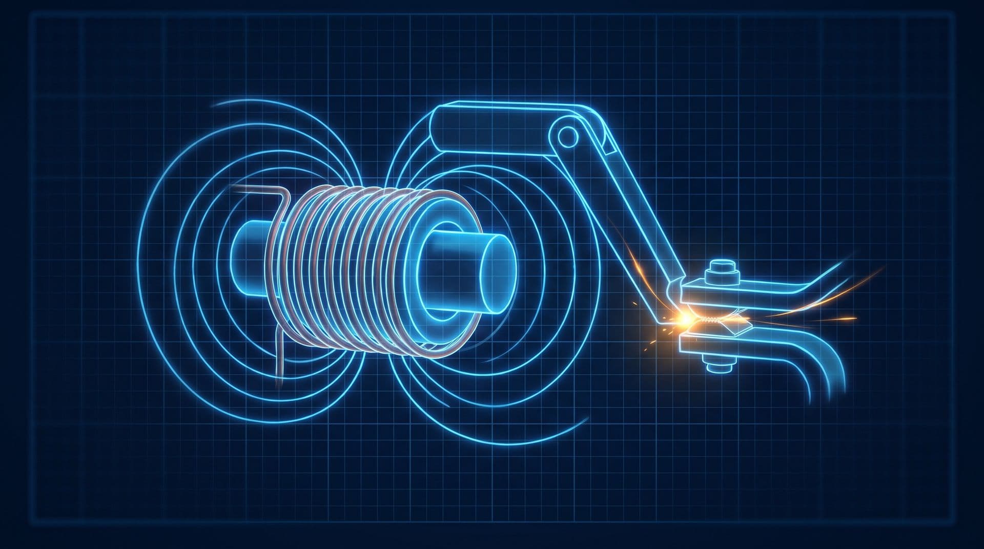
So what if we wind the wire into a coil? Now the field from every turn adds up inside it, and if we put iron in the middle, the field gets hundreds to thousands of times stronger. That's what we call an electromagnet.
In a coil, each turn's circle of field points the same way through the centre, so the turns add together. A coil of 1,000 turns carrying 0.04 A makes roughly the field of one turn carrying 40 A. Then the iron does the rest. Its atoms behave like tiny magnets, normally pointing every which way, and the coil's field lines them up so their combined field adds to the coil's own.
An electromagnet pulls on nearby iron, so let's hinge a small iron plate just above the core and hold it up with a spring. We call that plate the armature. With the coil off, the spring wins. Switch the coil on and the field pulls the armature down, and as the gap shrinks the pull gets stronger, so instead of drifting, the armature snaps shut with a click. Switch the coil off, the field collapses, and the spring throws the armature back. So that's force from current, and it's the first time in this course that electricity has actually moved something.
How does a relay work
Now we can build the relay. It's basically Part 4's switch with an electromagnet to flip it. Current in the coil pulls the armature, the armature pushes a set of contacts, and those contacts open or close a second, separate circuit.
So a relay has two sides with no wire between them. The coil side might run on a steady 24 V from a controller, and the contact side might switch the 230 V mains to a lamp, a valve or another, bigger coil. The only link is the magnetic pull, which also keeps the controller's low-voltage wiring isolated from the mains.
Let's work out the trade, using Ohm's law from Part 3 and power from Part 5. Take a 24 V relay coil with a resistance of 600 Ω. That's an illustrative round figure. Omron's MY series of small control relays lists 650 Ω and about 0.9 W for its 24 V direct-current coil (Omron MY datasheet):
$$I = \frac{24\ \text{V}}{600\ \Omega} = 0.04\ \text{A} \qquad P = 24\ \text{V} \times 0.04\ \text{A} \approx 1\ \text{W}$$
If the contacts are rated 10 A at 230 V, that 1 W of coil power controls up to 2,300 W.
Relay contacts come in two kinds, named for their resting state with the coil switched off:
- A normally open (NO) contact is open at rest and closes when the coil is energised.
- A normally closed (NC) contact is closed at rest and opens when the coil is energised.
Many relays have a changeover set, a common terminal that touches the NC terminal at rest and swings across to the NO terminal when the coil pulls in. And "normally" here means de-energised, not "usually". Engineers choose between the two by asking what should happen if the control signal is lost, so that a dead coil leaves the equipment in its safe state.
A small relay takes up to about 20 milliseconds to change over, and you can actually hear every one.
Relay logic
Back in Part 4, someone had to flip both switches by hand, right beside the lamp. So what if instead of flipping switches by hand, we replace them with relays and flip them from far away? Well, if we wire relay contacts the way Part 4 wired switches, they start making decisions. Two contacts in series pass current only if both are closed, and that's AND. Two contacts in parallel pass current if either one is closed, and that's OR. We can lay out every case in a little table, where 1 means a closed contact, or current flowing:
Contact A | Contact B | A and B in series (AND) | A and B in parallel (OR) |
|---|---|---|---|
0 | 0 | 0 | 0 |
0 | 1 | 0 | 1 |
1 | 0 | 0 | 1 |
1 | 1 | 1 | 1 |
Every case is there with no gray area, and that's what we call a truth table. An NC contact adds a third operation, NOT, because current flows only while its relay is off. And with AND, OR and NOT, we can build any yes-or-no rule out of relays.
I'll be honest, logic made of clicking relays sounded like a toy to me at first. But in buildings it does serious work as interlocks, which are safety rules wired in copper that hold whatever the software wants. A duty pump and its standby pump can each be wired through an NC contact of the other's contactor, so they can never both run.
The seal-in circuit
Now there's one more wiring trick, and it turns logic into memory. Put a stop button (NC) in series with a start button (NO), then the coil. Then wire one of the coil's own NO contacts in parallel with the start button, so the relay's own output is fed back to keep itself on.
- Press start. The coil energises, the motor runs, and the coil's own contact closes.
- Let go. The start button springs open, but current now flows through that contact, so the coil holds itself on.
- Press stop. The NC button opens, the coil drops, its contact opens, and it stays off.
- If the supply fails, or dips too low to hold the coil, the coil drops and the latch breaks. Nothing restarts by itself when power returns, which is deliberate.
So the circuit's output now depends on what happened before, as well as on what the buttons are doing right now, and that's what memory is. One sealed-in relay holds one of Part 4's bits, 1 for running and 0 for stopped. The drawing of this rung on a real panel is covered in how to read control wiring diagrams.
Relays do have limits, though. Every click wears the contacts a little, and they're slow. The Omron relay above is rated for at most five operations a second with no load, and one every two seconds when switching its full rated load. Part 15 replaces the moving armature with a switch that has no moving parts.
Contactors, starters and breakers
In a building, the relay idea shows up at three sizes, as control relays for signals, contactors for motors, and the magnetic trip inside most breakers.
A contactor is basically a relay built for motor currents. It has three heavy main contacts, one for each supply wire of a three-phase motor (Part 10), plus small auxiliary contacts that report what it's doing. And the size brings one new problem. Contacts that open while carrying 20 A don't stop the current at once, because it jumps the widening gap as an arc hot enough to burn metal. So contactors split each break into two gaps and use arc chutes to stretch and cool the arc, and that heavy mechanism makes the clunk you hear from a plant room panel (inside an electrical control panel).
A contactor, an overload relay and a breaker together make a motor starter, and rows of starters, one per fan or pump, fill a motor control centre (MCC) in the plant room.
The same kind of coil sits inside a circuit breaker too. In Part 4, a short drove 460 A through a 20 A breaker. That current flows through a small coil in the breaker, and its field yanks a trip latch open within milliseconds (circuit breaker types explained). Part 14 puts this trip together with the breaker's slower, heat-driven one.
The relay is also how a BMS protects the maximum demand from Part 5. When the half-hour is heading over target, the BMS opens relays to shed or delay loads that can wait (load shedding and demand limiting).
Starting an AHU fan
So let's follow the 7:30 a.m. start from the opening, step by step. A BMS starts a fan through a chain of electromagnets, each one switching a bigger one.
- The BMS controller's digital output (DO), a single on/off point, puts 24 V on the coil of a small interface relay in the AHU's motor control panel, and about 40 mA flows.
- The interface relay's NO contact closes. It sits in series in the contactor's coil circuit, along with the overload relay's NC contact, an NC contact from the fire alarm interface relay, and a Hand-Off-Auto selector switch set to Auto. All four have to be closed, so that's a four-input AND.
- The contactor's coil pulls in with a clunk. Its three main contacts close and 400 V reaches the 11 kW fan motor, which draws roughly 20 A on each wire.
- One of the contactor's auxiliary NO contacts closes too. It's wired back to a BMS digital input (DI), so the BMS sees "fan running". If the command is on but the status never arrives, the BMS raises an alarm.
In Hand, the panel runs the fan locally from start and stop push buttons with a seal-in contact, so a technician can test it with the BMS offline. And if the fire alarm activates, its relay opens the AND chain and the fan stops, whatever the BMS wants, so the AHU doesn't spread smoke around the building.
Now let's count the gain. About 1 W at the BMS output controls about 12 kW of motor input, roughly 12,000 to 1, through two electromagnets in a row. On many newer AHUs the contactor feeds a variable speed drive (Part 15), but the start command still travels through relay contacts. Part 11 opens up the motor itself.
Motion and current
So far this part has run one way, with current in and motion out. A coil's field pulled an armature, and a contactor's pull started a fan.
Now let's turn it around. If a current can make a magnet move iron, can a moving magnet make a current? Michael Faraday found the answer in 1831, and it's how nearly every power station makes electricity. We'll build it in Part 7.
Go deeper (optional). This video shows a relay's coil, armature and contacts at work, one moving part at a time.
"How Relays Work - Basic working principle" by The Engineering Mindset
For the rest of the hardware in a motor panel, read inside an electrical control panel.
This is Part 6 of 23 in Cobler's Electricity Fundamentals course. Previous: Power vs Energy: kW and kWh. Next: Generators and Induction.
Cobler's CobiNeural reads the run commands and status points of a building's fans and pumps alongside its energy data, so request a demo to see your plant's starts and stops live.
FAQ
Frequently asked questions
Ask us about this topic
Something in this article you want to dig into — or a situation in your own building it doesn't quite cover? Send us your question. We don't run public comments; the team replies to you directly by email.