Blog
Sensors and 4-20 mA Signals
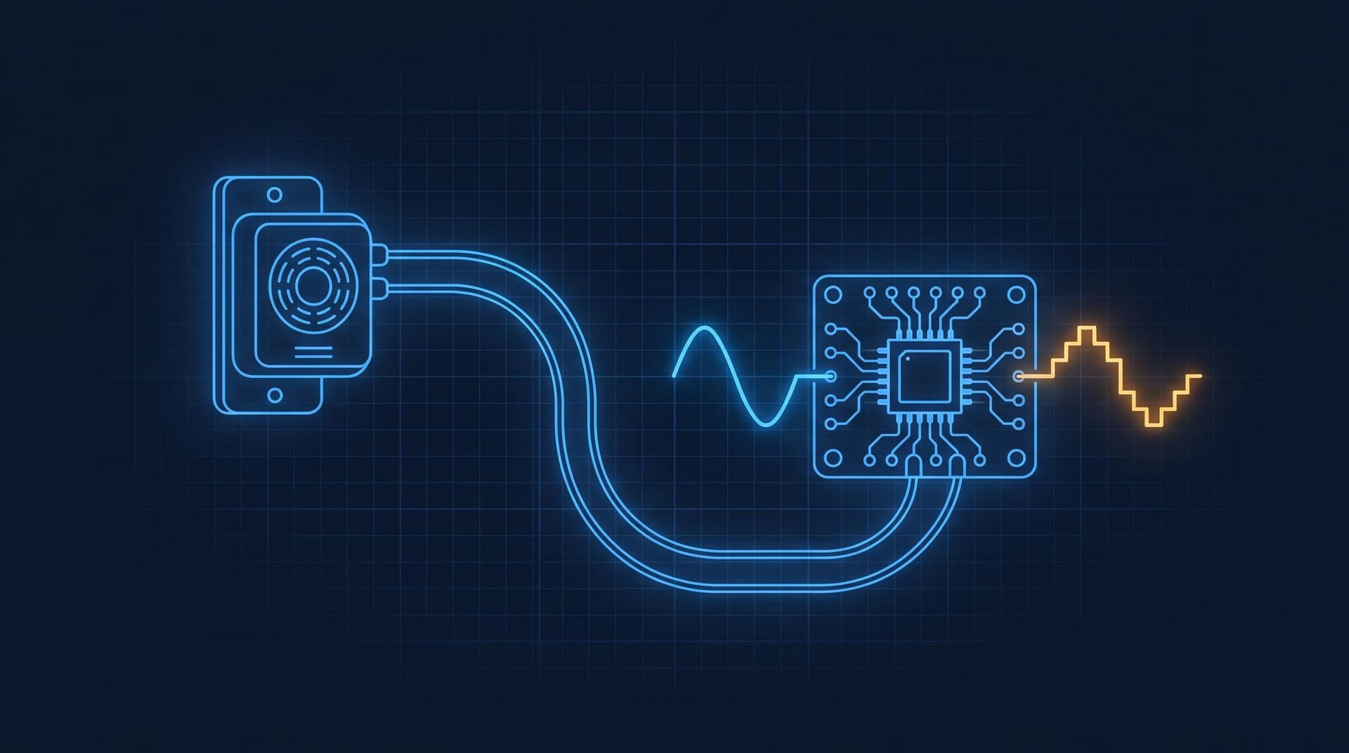
How a building turns CO2 and temperature into numbers: the sensor changes resistance or light, a 4-20 mA loop carries it without losing accuracy on long cables, and an analog-to-digital converter writes it as bits. Worked: 12 mA means 1,000 ppm.
 Tan Kok XinElectricity Fundamentals
Part 20 of 23 in Cobler's Electricity Fundamentals course. New here? Start with the course map.
At the end of Part 19 we clamped current transformers onto the chiller feeder, and now the meter knows the electricity: volts, amps, kW, kWh and power factor. But half of what matters in a building isn't electrical, things like temperature, carbon dioxide (CO2), flow and pressure. So to measure those, we first have to turn them into electricity, very often as a small current in a pair of wires called a 4-20 mA signal.
Let's watch one of them at work. It's 10 a.m., and twelve people walk into a level 9 meeting room in our office tower and shut the door. Every breath out adds a little CO2. Twenty minutes later a small box on the wall reads 900 parts per million (ppm), and down the corridor a fresh-air damper has swung wide open, and nobody touched a switch. So what happened in between? Well, the gas changed a current in a pair of thin wires, and the current became a number. Let's follow it from the sensor to the bits.
Sensors
So a controller can't feel heat or smell CO2. All it can measure is volts and amps (Part 2). That means we need a go-between, a part whose electrical behaviour changes with what we want to measure, and we call that a sensor.
The simplest ones are just switches, like a fan's airflow switch, which is open or closed. Temperature takes a bit more, and you already know how. In Part 3 we saw that a metal's resistance goes up as it warms, because the hotter atoms vibrate more and get in the electrons' way. A platinum sensor called a PT1000 is built on exactly that. It measures 1,000 ohms at 0 °C and rises by about 3.85 ohms for every degree. So in chilled water at 7 °C it reads:
$$R = 1000 \times (1 + 0.00385 \times 7) \approx 1027 \ \Omega$$
Many room and duct sensors use a thermistor instead. It's made from a semiconductor material, and its resistance usually falls as it warms, which we call a negative temperature coefficient, or NTC, and it changes much more steeply than platinum. A common type reads 10,000 ohms at 25 °C.
Voltage dividers
My first guess was that we'd just need a conversion chart: read 1,027 ohms, look up 7 °C, done. But that skips a step. The controller's input only ever measures a voltage, so the resistance has to become a voltage first.
So how do we do that? Well, we put the sensor in series with a fixed resistor across a steady voltage, and that's what we call a voltage divider. The same current flows through both (Part 4), so Ohm's law splits the voltage in proportion to the resistances:
$$V_{out} = V_{in} \times \frac{R_{sensor}}{R_{fixed} + R_{sensor}}$$
If we put 5 V across a 10,000-ohm thermistor and a 10,000-ohm fixed resistor, then at 25 °C \(V_{out}\) is exactly 2.5 V. Warm the room and the thermistor's resistance drops, so \(V_{out}\) drops too, and the sensor's published curve turns that voltage back into degrees.
CO2 and pressure sensors
Other quantities take one more step. A CO2 sensor uses what's called non-dispersive infrared (NDIR) light. Basically, a tiny lamp shines infrared through a chamber of room air, and CO2 molecules absorb light at a wavelength of about 4.26 micrometres. A detector behind a filter measures what gets through, so more CO2 means less light and a smaller signal.
Many pressure sensors use a thin diaphragm that bends and stretches a strain gauge, a foil pattern whose resistance rises as it gets longer and thinner (Part 3's \(R = \rho L / A\) again). In both cases, electronics inside the box turn the raw signal into a standard output, usually 0-10 V or 4-20 mA.
4-20 mA current loops
Now, the CO2 reading has to reach a controller somewhere else, and a lot of building sensors send it as a current instead of a voltage. The reason goes back to Part 4: the current is the same at every point of a series loop, so the cable can't change the reading, while a voltage signal can get shifted on its way.
In a 4-20 mA loop, the sensor, which we call a transmitter, sits in one series loop with a 24 V DC supply and a small resistor inside the controller. The transmitter adjusts the loop current to match what it measures, so 4 mA at the bottom of its range and 20 mA at the top. For a CO2 sensor ranged 0 to 2,000 ppm:
$$\text{CO}_2 \ (\text{ppm}) = \frac{I - 4}{16} \times 2000$$
So 12 mA means (12 − 4) ÷ 16 × 2,000 = 1,000 ppm.
Now let's run that loop 300 m from a meeting room to a plant room. The cable does cost some voltage. If the pair is 0.5 mm² copper, 600 m there and back is about 21 ohms, so at 20 mA it drops 20 mA × 21 Ω ≈ 0.4 V (Part 3). But the transmitter doesn't really care. It forces the current it wants around the loop and just uses a little less of the 24 V. As long as there's enough voltage left to run it, every metre of the loop carries the same current (illustrative cable figures). It's kind of like a pump set to deliver ten litres a minute through a garden hose. A longer hose makes it push harder, but ten litres a minute still reach the nozzle.
A 0-10 V signal doesn't get that protection. It's read against the controller's 0 V, and on a long run the 0 V at each end can differ slightly, while nearby power cables induce noise. On a 0-2,000 ppm range, an error of just 0.1 V is 20 ppm, and nothing warns you.
Live zero
Now here's something kind of clever. Starting the range at 4 mA instead of 0 actually pays off twice. A healthy loop never reads zero, so if the cable is cut, the current falls to 0 mA, which no real CO2 level can produce, and the controller raises a sensor fault. A broken 0-10 V wire reads 0 V, which looks like a believable 0 ppm. Engineers call this a "live zero". The 4 mA floor also lets many transmitters power themselves from the loop's own two wires.
So the reading arrives intact. But a processor can't store a current. So how do we go from a current on a wire to a number in memory? Well, what if we turn it back into a voltage, then ask which of a few thousand fixed steps it sits on?
Analog-to-digital conversion
That's basically what an analog-to-digital converter (ADC) does. It measures a voltage, rounds it to the nearest of a fixed number of steps, and writes the step number in binary.
First, the current becomes a voltage. The controller's input passes the loop current through a 250-ohm resistor, and Ohm's law does the rest: 4 mA gives 1 V, 20 mA gives 5 V, and our 12 mA gives 12 mA × 250 Ω = 3 V.
Then the ADC samples that voltage many times a second and compares it with a reference, here 5 V. A 12-bit ADC splits the range into \(2^{12}\) = 4,096 steps, each 5 V ÷ 4,096 ≈ 1.22 mV wide, and reports which step the voltage falls in. If 5 V were a wall 5 metres tall, each step would be about 1.2 mm.
Finally, it writes the step number as bits. Each bit is one of Part 4's switches, open (0) or closed (1), built from the transistors of Part 15. With twelve of them we can hold any count from 0 to 4,095.
Let's work one backwards. Say the controller reads a count of 2,048, which in binary is 1000 0000 0000, so one switch on and eleven off.
$$V = 2048 \times \frac{5}{4096} = 2.5 \ \text{V} \quad\Rightarrow\quad I = \frac{2.5}{250} = 10 \ \text{mA} \quad\Rightarrow\quad \frac{10 - 4}{16} \times 2000 = 750 \ \text{ppm}$$
We can make a little table for the whole range:
Loop current | Volts across 250 Ω | 12-bit count | CO2 reading |
|---|---|---|---|
0 mA | 0 V | 0 | Fault: broken wire |
4 mA | 1.0 V | 819 | 0 ppm |
10 mA | 2.5 V | 2,048 | 750 ppm |
12 mA | 3.0 V | 2,458 | 1,000 ppm |
20 mA | 5.0 V | 4,095 | 2,000 ppm |
You can also see what the live zero costs us. Counts 0 to 818, a fifth of the ADC's range, sit below 4 mA and never carry a CO2 reading. Designers accept that because the 3,277 counts left are plenty. One count is worth about 0.6 ppm, far finer than the sensor itself can measure. And a count can be copied, stored and sent without losing accuracy.
So this is where the course's digital thread arrives. The switch of Part 4 became the relay of Part 6 and then the transistor of Part 15, and now twelve of them side by side hold a measurement of the air in a room.
AI, AO, DI and DO
Every wire into or out of a building controller is one of four point types. The ADC handles the first, and the others are the same ideas reversed or in on/off form.
- Analog input (AI): a reading on a range, like the CO2 sensor's 4-20 mA or a PT1000's resistance.
- Analog output (AO): the same trip in reverse. A digital-to-analog converter turns a number into 0-10 V, which sets a damper actuator's position or a drive's speed.
- Digital input (DI): a contact that's either open or closed, like that fan's airflow switch or a breaker's trip contact.
- Digital output (DO): the controller energises a 24 V relay coil from Part 6, which starts a fan or a pump.
A direct digital control (DDC) controller is basically a box of these points plus a processor running the sequence. Controllers, DDC and I/O points covers how they're specified, and BMS sensors and actuators covers the hardware at each end of the wire.
Demand-controlled ventilation
So back to the level 9 meeting room. The CO2 sensor on the wall sends 4-20 mA down a twisted pair to the controller of the floor's air handling unit (AHU). With the room empty, the loop sits at about 7.6 mA, or 450 ppm, just above outdoor air. The US National Oceanic and Atmospheric Administration measured about 426 ppm at its Mauna Loa station in September 2026 (NOAA CO2 trends).
Then the meeting starts and the reading climbs. The controller's sequence (illustrative) starts opening the fresh-air damper at 600 ppm and has it fully open by 900 ppm, which on the loop is 4 + 16 × 900 ÷ 2,000 = 11.2 mA. A second analog output asks the AHU fan's variable speed drive (Part 15) for more speed to push the extra air. The room levels off below 1,000 ppm. That's the limit in Malaysia's Industry Code of Practice on Indoor Air Quality 2010, and above it the code treats the ventilation as inadequate (what the ICOP requires). When the meeting ends, the CO2 falls back and the damper and fan ease off. So the room gets fresh air in proportion to the people actually in it, and that's what we call demand-controlled ventilation (DCV).
So why don't we leave the damper open all day? Well, outdoor air in Kuala Lumpur is hot and wet, and the chiller plant has to cool and dry every litre. At 10 litres per second per person (illustrative), twelve people need 120 L/s. Taking that much 33 °C humid air down to 13 °C off the coil removes about 48 kJ per kg of air, which is roughly 6.7 kW of cooling for one meeting room. With DCV we only pay that cost while the room is full. What CO2 really tells you and ventilation rates for Malaysian offices go further.
Sending the number on
So now the AHU controller holds 900 ppm as a 12-bit count. But the building management system (BMS) server sits in the basement control room, the analytics run somewhere else, and the chiller plant's thirty power meters, each like the one in Part 19, hold their own numbers. A separate 4-20 mA pair from every number to every place that needs it would take thousands of cables. So how do we get it out of that one controller? Well, what if it travels as bits, with lots of devices sharing one wire? That's Part 21: Modbus RTU and RS-485.
Go deeper (optional)
"Digital Electronics - The First Video YOU Should Watch" by CaptiveAire
This is the video the course is modelled on. It goes from a light switch to relays, transistors and memory, then sensors, analog-to-digital conversion and Modbus in buildings. For the switch-to-processor story, read From Transistor to CPU.
This is Part 20 of 23 in Cobler's Electricity Fundamentals course. Previous: Current Transformers and Power Meters. Next: Modbus RTU and RS-485.
Cobler builds CobiNeural, which reads a building's CO2, temperature and energy sensors as live numbers and flags the ones that drift. To see it on your own site, request a demo.
FAQ
Frequently asked questions
Ask us about this topic
Something in this article you want to dig into — or a situation in your own building it doesn't quite cover? Send us your question. We don't run public comments; the team replies to you directly by email.