Blog
The Processor: Fetch, Decode, Execute
Who decides which sum comes next? Part 5 builds the fetch decode execute cycle on a toy computer: instructions stored as numbers, a program counter, decoding as plain wiring, and a jump that makes decisions, running a building's CO2 damper program one tick at a time.
 Tan Kok XinHow a Computer Works

Part 5 of 13 in Cobler's How a Computer Works course. New here? Start with the course map.
At the end of Part 4 we had an ALU, some registers and a memory full of numbered rows on the bench, and us standing over them setting every switch by hand. So who takes over that job? Well, every processor, from the 2,300 transistors of Intel's 4004 in 1971 to the 28 billion of Apple's M4 in 2024, does it with the same small loop, repeated over and over. It's called the fetch decode execute cycle, and once we've built it, the computer can run by itself.
A list of steps
Let's start with a real job for it. The level 9 AHU controller's fresh-air damper sequence, written as plain steps, goes something like this (illustrative):
- Read the CO2 reading.
- If it's below 600 ppm, set the damper to 0%.
- Otherwise, set the damper to (CO2 − 600) ÷ 3 percent. The gap from 600 to 900 ppm is 300, and dividing by 3 turns that 300 into 100%.
- Send the damper position out, and go back to step 1.
Each of those steps is something our parts can already do. Reading is copying a number out of a row of memory. "Below 600?" is a compare. The damper percentage is a subtract and a divide. And sending it out is copying a number into a row. What's missing is something that does them in order, one after another, without us.
An instruction is a number
This is where the odd thing we noticed about bytes in Part 1 comes back. What if the steps themselves are numbers, stored in the same memory as the data?
To see it, let's build a toy computer. We've made it up for this course, but it works the way real ones do. It has 16 memory slots, numbered 0 to 15, so a 4-bit address picks any one of them with the decoder from Part 4. It has one register to work in, called register A, and a one-bit flag that keeps the top bit from the last subtract or compare. And it has Part 3's ALU, with the same chooser codes. (A real chip's slots all hold the same number of bits. Our toy lets a slot hold any whole number, so that readings like 750 fit.)
Each instruction is an 8-bit number. The first four bits say which job to do, and the last four say which memory slot to do it with. Our toy knows eight jobs:
- LOAD (0001) copies the number in the slot into register A.
- STORE (0010) copies register A into the slot.
- ADD (1000), SUBTRACT (1001), COMPARE (1010) and DIVIDE (1011) send register A and the slot's number through the ALU. SUBTRACT and COMPARE set the flag, and every one of them except COMPARE puts its answer back in register A.
- JUMP (0100) makes the slot's instruction the next one to run.
- JUMP-IF (0101) does the same, but only if the flag is 1.
So LOAD 15 is 0001 then 1111, which is the number 31. And remember 65 from Part 1, the letter A, 0100 0001? Read as a toy instruction, it's 0100 then 0001, which is JUMP 1. The byte still doesn't know what it is. It's an instruction only because the processor fetches it as one.
The damper program
Now let's write the damper sequence in toy instructions. The program sits in slots 0 to 8. Slot 11 holds 0, slot 12 holds the 600 ppm setpoint, and slot 13 holds 3. Slots 14 and 15 are the damper output and the CO2 input, and we'll come back to those two.
Slot | Instruction | As a number | What it does |
|---|---|---|---|
0 | LOAD 15 | 0001 1111 (31) | Put the CO2 reading in register A |
1 | COMPARE 12 | 1010 1100 (172) | Is A below 600? The flag says |
2 | JUMP-IF 7 | 0101 0111 (87) | If it is, go to slot 7 |
3 | SUBTRACT 12 | 1001 1100 (156) | A becomes CO2 − 600 |
4 | DIVIDE 13 | 1011 1101 (189) | A becomes A ÷ 3 |
5 | STORE 14 | 0010 1110 (46) | Send A out as the damper % |
6 | JUMP 0 | 0100 0000 (64) | Back to the start |
7 | LOAD 11 | 0001 1011 (27) | Put 0 in register A |
8 | JUMP 5 | 0100 0101 (69) | Go and send it out |
So to the processor, the whole program is this list of numbers: 31, 172, 87, 156, 189, 46, 64, 27, 69. Notice too that the toy keeps 3 in slot 13 instead of the 900 ppm setpoint. (900 − 600) ÷ 100 is 3, and storing that saves a step every time round. The toy's DIVIDE is a simplification too, since a real ALU needs a longer circuit or a loop of subtractions to divide.
The fetch decode execute cycle
Now we need the part that runs the list. It has two more registers. The program counter holds the address of the next instruction, and it starts at 0. The instruction register holds the instruction being worked on. Then, on each tick of the clock from Part 4, the processor does the next of three steps.
Fetch. The program counter's address goes onto the memory's address wires, the decoder lights up that one slot, and its number comes out on the data wires and into the instruction register. At the very start, that's slot 0's 31.
Decode. Now, you'd think something has to read the instruction and work out what it means. But nothing reads it. Its bits are simply wired to the parts they control. The first bit switches the ALU on. The last two bits of the job go straight to the ALU's chooser, which is why ADD, SUBTRACT, COMPARE and DIVIDE end in 00, 01, 10 and 11, the chooser codes from Part 3. And the last four bits go onto the memory's address wires, to pick the slot. So decoding is basically wiring, plus a gate or two.
Execute. Then the parts do their job. For COMPARE 12, the ALU subtracts slot 12's 600 from register A and keeps the top bit in the flag. For STORE 14, register A gets written into slot 14. And the program counter moves on to the next address by adding 1, on the same kind of adder we built in Part 3, so 0011 + 0001 gives 0100.
Then it fetches again, and round it goes. That loop is the fetch decode execute cycle, which is also called the instruction cycle. And the block that runs it, with its program counter, decoding wires, ALU and registers, is what we call the processor, or the CPU (central processing unit). If you've read Electricity Part 21, this is the same loop, slowed right down.
Jumps
But a list that only ever goes forwards would run once and stop, and it could never make a choice. That's what jumps are for. JUMP puts its four slot bits into the program counter, instead of letting it add 1, so the next fetch comes from wherever the jump says. JUMP 0 in slot 6 sends the program back to the start, and that's how a program loops.
JUMP-IF is the same, with one more gate in the way. The new address only goes into the program counter if the flag is 1. And that one gate is how a list of numbers makes a decision.
So let's run it at 750 ppm. LOAD 15 puts 750 in register A. COMPARE 12 works out 750 − 600 = 150, so the top bit is 0 and so is the flag. JUMP-IF 7 sees the flag at 0 and doesn't jump, so the program counter just adds 1. SUBTRACT 12 makes A 150, DIVIDE 13 makes it 50, and STORE 14 sends 50% to the damper. Then JUMP 0 starts it all again.
Now let's try 550 ppm. COMPARE works out 550 − 600 = −50, so the top bit is 1 and the flag is 1, and this time JUMP-IF sends the program counter to 7. LOAD 11 puts 0 in register A, JUMP 5 goes back to the STORE, and the damper gets 0%. It's the same list of numbers, with a different path through it, decided by one bit. (Our toy's CO2 only goes from 400 to 900 ppm, so it never needs the real controller's cap at 100%.)
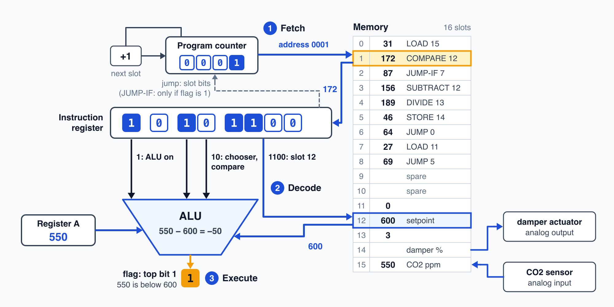
COMPARE 12 is the number 172, whose bits go straight onto wires that switch on the ALU, pick its job and pick slot 12.
Try it. Run the program by hand at 840 ppm. What does the damper get, and which slots run?
Show the worked answer
LOAD 15 puts 840 in register A. COMPARE 12 works out 840 − 600 = 240, which isn't below zero, so the flag is 0 and JUMP-IF doesn't jump. SUBTRACT 12 makes A 240, DIVIDE 13 makes it 80, and STORE 14 sends 80% to the damper. Then JUMP 0 goes back to the start.
So slots 0, 1, 2, 3, 4, 5 and 6 run, and slots 7 and 8 are skipped.
Try it. Which toy instruction is the number 140, and what would it do?
Show the worked answer
140 is 128 + 8 + 4, so in eight bits it's 1000 1100. The first four bits, 1000, are ADD, and the last four, 1100, are slot 12. So it's ADD 12. It would add slot 12's 600 to whatever is in register A and put the answer back in A.
Billions of steps a second
Our toy spends three ticks on each instruction, one each to fetch, decode and execute, so one pass of the damper program is 7 × 3 = 21 ticks. A laptop processor ticks a few billion times a second. At 3 billion a second (illustrative), that's
$$\frac{21 \ \text{ticks}}{3{,}000{,}000{,}000 \ \text{ticks per second}} = 0.000000007 \ \text{s}$$
or 7 billionths of a second for the whole pass. Real processors are cleverer than our toy, too. They overlap the steps, fetching the next instruction while the last one is still executing, and they can finish several instructions in one tick. But underneath, they're still running the same fetch, decode and execute loop as our toy.
And a program really is just a list of numbers. Our damper program is nine of them, and the browser on the facility manager's laptop is many millions, stored and fetched the same way. The M4's 28 billion transistors are about twelve million times the 4004's 2,300, and much of that goes into doing many steps at once and keeping numbers close at hand.
The level 9 damper
So let's go back to the level 9 AHU controller one more time. Its processor is a real one, often a small microcontroller, which is a processor with its own memory and input and output pins on one chip. Its instruction numbers are its own, and its program is far longer than ours, but it runs exactly this loop. At 10 a.m. the meeting room fills up and the CO2 climbs past 600, and on the next pass the JUMP-IF stops jumping and the damper starts to open.
Now look again at slots 14 and 15 in our toy. Our program never stores anything in slot 15, and never reads slot 14 back, because those two slots are wired to the outside. Slot 15 is connected to the analog input, so whatever the CO2 sensor's converter has measured shows up there as a number. (In the real controller that number is the 12-bit count from Electricity Part 20, which the program turns into ppm first. Our toy skips that step.) Slot 14 is connected to the analog output, so writing 50 there sets the signal to the damper's actuator.
That's called memory-mapped input and output. To the processor, the CO2 sensor and the damper are just more memory, two more numbers at addresses. That's the idea from the course map starting to arrive, the outside world as more memory. Hold on to slots 14 and 15, because in Act 2 we'll keep finding the same trick inside the laptop.
Where the list comes from
So that's Act 1. We started with one light switch, and now we have a processor that runs a list of instructions by itself. But we cheated a little at the start. Our toy's program was already sitting in slots 0 to 8 when we switched it on, and its program counter just happened to start at 0. A real laptop's memory is RAM, and in Part 4 we saw that RAM comes up with nothing useful in it when the power comes on. So where does the list come from, and what starts it running when you press the power button? That's where Act 2 begins, with Part 6: Programs and the Operating System.
This is Part 5 of 13 in Cobler's How a Computer Works course. Previous: Memory: Latches, Registers and RAM. Next: Programs and the Operating System.
Cobler builds CobiNeural, which reads a building's CO2, temperature and energy sensors as live numbers and flags the ones that drift. To see it on your own site, request a demo.
FAQ
Frequently asked questions
Ask us about this topic
Something in this article you want to dig into — or a situation in your own building it doesn't quite cover? Send us your question. We don't run public comments; the team replies to you directly by email.