Blog
Logic Gates
How can one switch flip another? Part 2 builds logic gates from a lamp and two switches, then relays, then transistors: AND, OR and NOT as truth tables, why NAND alone can build every other gate, and the copper interlock that stops two chiller plant pumps running together.
 Tan Kok XinHow a Computer Works

Part 2 of 13 in Cobler's How a Computer Works course. New here? Start with the course map.
Part 1 ended with rows of switches holding numbers, and a problem. Every switch needed a hand to flip it, so the numbers just sat there. So how can one switch flip another? Once it can, we can build the small deciding circuits called logic gates that every computer is made of, and a good place to see why we need them is the plant room of our office tower.
Down there, two condenser water pumps stand side by side, CWP-1 and CWP-2, the same CWP-2 from the 2 a.m. alert. One is the duty pump and the other is the standby, a spare that takes over if the first one fails, and they're wired so they can never both run. That rule is a decision. If CWP-1 is running, CWP-2 must not start. So how do switches make a decision like that, with nobody's hand on them? Well, let's start with the simplest version we can build, a lamp and two switches.
Two switches and a lamp
Let's wire a lamp, a battery and two switches, A and B, all in one loop, one after the other. That's called wiring them in series. Now let's go through every case. With both switches off, the lamp is dark. A on and B off, it's still dark, because the current can't get past B. A off and B on, dark again. Both on, and the lamp lights. So the lamp only lights when A and B are both on.
Now let's put the two switches side by side instead, so the current can go through either one. That's wiring them in parallel. This time the lamp is dark only when both are off, and it lights if A or B, or both, are on.
We can lay all of that out in a little table, writing 1 for a switch that's on or a lamp that's lit, and 0 for off:
A | B | In series (A AND B) | In parallel (A OR B) |
|---|---|---|---|
0 | 0 | 0 | 0 |
0 | 1 | 0 | 1 |
1 | 0 | 0 | 1 |
1 | 1 | 1 | 1 |
Every case is there, with no gray area, and a table like this is what we call a truth table. The series circuit gives us AND, and the parallel one gives us OR.
There's one more we need. Picture a push button wired the other way round, so that pressing it breaks the circuit instead of closing it. Now the lamp is lit when the button is 0 and dark when it's 1. The output is just the opposite of the input, and we call that NOT.
Relays
But somebody still has to press every switch. So how do we go from switches flipped by hand to switches flipped by a signal? Well, what if the switch is flipped by a magnet?
Let's wind some wire around an iron core. When current flows through the coil, the core becomes a magnet, which we call an electromagnet, and it pulls a springy metal arm towards it. The arm pushes a pair of contacts together, and that closes a second, separate circuit. Switch the current off, and the spring pulls the arm back and the contacts open again. That's a relay. Some relays have contacts that are open at rest and close when the coil is on, which we call normally open, and some have contacts that are closed at rest and open when the coil is on, called normally closed. If you've read Electricity Part 6, this is that same relay.
Now, a relay's contacts can just as easily carry the current for another relay's coil. So the output of one relay becomes the input of the next, and now switches really are flipping switches. Wire two relays' contacts in series and the next coil only gets current if both are on, which is AND. Wire them in parallel and we get OR, and a normally closed contact gives us NOT. A little circuit like this, which answers one yes-or-no question about its inputs, is what we call a logic gate.
Relays have two problems, though. They're slow, because the arm has to physically move. A small relay takes up to about 20 milliseconds to change over, and the one in Electricity Part 6 is rated for at most five operations a second. And every click wears the contacts a little. Some of the first computers, in the 1940s, were built from relays anyway. ENIAC, unveiled in 1946, used about 18,000 vacuum tubes instead, which switch in around a millionth of a second but run hot and burn out.
Transistors
So what if we get rid of the moving parts altogether? That's what a transistor does. The first one was made at Bell Labs in 1947, and the kind used in chips today works like this. It's a switch made of silicon. A small voltage on one of its terminals, called the gate, lets current flow through the silicon between the other two, and without that voltage the current stops. Nothing moves, so nothing wears out. Electricity Part 15 uses big ones to switch motor currents, and on a chip they're far smaller than a bacterium.
We can put numbers on how far that gets us. The relay manages about five operations a second. A laptop's processor ticks a few billion times a second, and its transistors keep up. That's hundreds of millions of times faster, in a switch far too small to see.
Chips use two kinds of transistor that work as a pair. One kind turns on when its gate gets a voltage, which we'll call 1. The other kind does the opposite and turns on when its gate has no voltage, 0.
Logic gates in silicon
So let's build a NOT gate. We stack one of each kind between the supply (1) and 0 V, with the second kind at the top, next to the supply, and the first kind at the bottom, next to 0 V. We join their gates together as the input, and take the output from the point between them. When the input is 1, the bottom transistor turns on and the top one turns off, so the output is connected to 0 V and reads 0. When the input is 0, it's the other way round, and the output reads 1. That's NOT, from two transistors.
Notice that one of the pair is always off. So almost no current flows straight through them, except for a brief moment while they flip. This pairing is called CMOS (complementary metal-oxide-semiconductor), and it's why a chip with billions of transistors doesn't melt, because it only really uses energy when something changes.
Now let's build a gate with two inputs. We put two of the first kind in series between the output and 0 V, so the output only gets pulled down to 0 when both inputs are 1. And we put two of the second kind in parallel between the supply and the output, so a 0 on either input pulls the output up to 1. Let's go through the cases. 0 and 0 give 1. 0 and 1 give 1. 1 and 0 give 1. Only 1 and 1 give 0.
If we compare that with the AND column in our truth table, every answer is flipped. So it's an AND followed by a NOT, and we call it NAND. It takes four transistors.
NAND builds the rest
Now, here's something kind of surprising. NAND is the only gate we actually need. Tie its two inputs together, so both always get the same signal, and 1 gives 0 while 0 gives 1, so it's a NOT. Put that NOT after another NAND and the two flips cancel, so we're back to AND. And put a NOT in front of each input of a NAND, and we get OR. Let's check that one. If both inputs are 0, the NOTs turn them into 1 and 1, and the NAND gives 0. If either input is 1, its NOT turns it into a 0, and a NAND with any 0 going in gives 1. That's OR exactly.
So with nothing but NAND gates we can build any yes-or-no rule at all, just as we could with relays. And NAND is actually cheaper than AND. In CMOS an AND is built as a NAND with a NOT after it, which takes six transistors instead of four, so chip designers tend to think in NANDs.
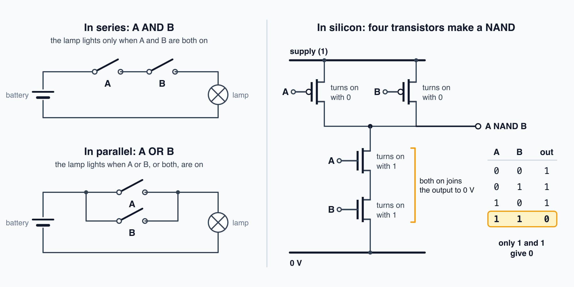
Switches in series make AND, switches in parallel make OR, and four transistors make a NAND that gives 0 only when both inputs are 1.
Try it. If we build an OR purely from NAND gates, the way we just did, how many NAND gates does it take, and how many transistors?
Show the worked answer
It takes three NAND gates. Two of them have their inputs tied together, acting as the NOTs, and the third combines them. At four transistors each, that's 3 × 4 = 12 transistors.
A chip designer would build the two NOTs from two transistors each instead, which gives 2 + 2 + 4 = 8.
Gates as decisions
So any rule we can say with "and", "or" and "not" can be wired from gates. An air handling unit's fan, for example, might be allowed to run if it's scheduled on AND the fire alarm is NOT active. That's one NOT and one AND.
We could even write a simple version of the 2 a.m. alert this way. Say we have one bit that's 1 when CWP-2 is running, and one bit for each of the plant's chillers, which we'll call C1, C2 and C3 (illustrative). Then the rule "CWP-2 running AND NOT (C1 OR C2 OR C3)" gives 1 only when the pump runs with every chiller off. The real alert came from software comparing the pump's power with what it expected, which takes more than one rule. But that software runs on a processor built from gates like these, as we'll see by Part 5.
The pump interlock
So let's go back to the plant room and wire the rule from the start. CWP-2 may run when it's asked to AND CWP-1 is NOT running, and CWP-1 has the same rule the other way round.
In the plant, each pump motor is started by a contactor, which is basically a heavy-duty relay for motor currents. Each contactor has a spare normally closed contact, and the other pump's coil is wired through it. So when CWP-1 runs, its contactor's normally closed contact opens, and CWP-2's coil can't get any current, whatever anything else asks for. That's NOT and AND, made from relay contacts in copper, and engineers call a safety rule like this an interlock.
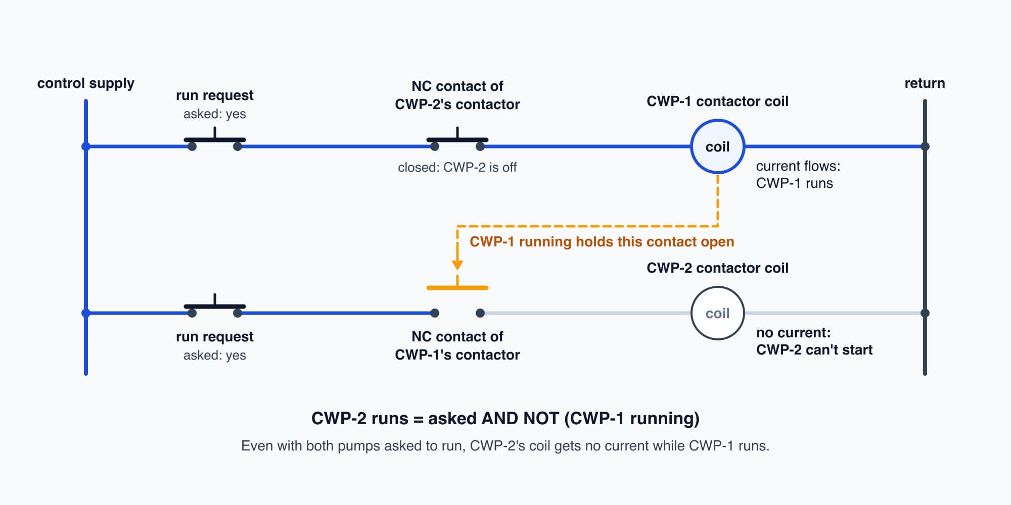
Each pump's coil runs through a normally closed contact of the other pump's contactor, so while one runs the other can't start.
The plant's controller has the same rule in its program, built from transistor gates, and it's what decides which pump is on duty (Part 12 opens that controller up). So why keep the copper version as well? Well, if the program has a bug, or the controller fails, the copper rule still holds. The software can ask for both pumps at once, and the relays simply won't let it happen.
Try it. Write CWP-2's rule as gates, and go through all four cases of "CWP-2 asked to run" and "CWP-1 running".
Show the worked answer
As gates, CWP-2 runs = asked AND NOT (CWP-1 running). So the four cases go like this.
- Not asked, CWP-1 off: 0, there's nothing to do.
- Not asked, CWP-1 running: 0.
- Asked, CWP-1 off: 1, so CWP-2 starts.
- Asked, CWP-1 running: 0. The NOT turns CWP-1's 1 into a 0, so the AND blocks the start, and that's the interlock at work.
Decisions without sums
So gates can make any yes-or-no decision we can describe. But a building needs more than yes and no. To know that CWP-2 used 108 kWh overnight, something has to work out 27 kW × 4 hours. And the controller that reads Part 1's CO2 sensor has to work out how far the reading is past 600 ppm. Those are sums, and so far all our gates can do is answer questions with a 1 or a 0. So can gates actually do arithmetic? That's Part 3: Adding in Binary.
Go deeper on video (optional)
This course is modelled on this video. Its first section does what we just did on a real bench, going from a lamp and two switches to relays, vacuum tubes and transistor gates. You don't need it for Part 3.
"Digital Electronics - The First Video YOU Should Watch" by CaptiveAire
For the same gates from the electricity side, read Electricity Part 21: Logic Gates and the CPU.
This is Part 2 of 13 in Cobler's How a Computer Works course. Previous: Bits and Bytes. Next: Adding in Binary: the Adder and the ALU.
Cobler's CobiNeural reads the run commands and status points of a building's pumps and fans alongside their energy data, so it can flag a pump running when it shouldn't be. To see your own plant's starts and stops, request a demo.
FAQ
Frequently asked questions
Ask us about this topic
Something in this article you want to dig into — or a situation in your own building it doesn't quite cover? Send us your question. We don't run public comments; the team replies to you directly by email.