Blog
How Does a Chilled-Water System Work? The Three Loops Explained
How does a chilled water system work? A plain-language guide to the two water loops plus one refrigerant loop that cool an entire building from one chiller.
 Tan Kok XinCooling Fundamentals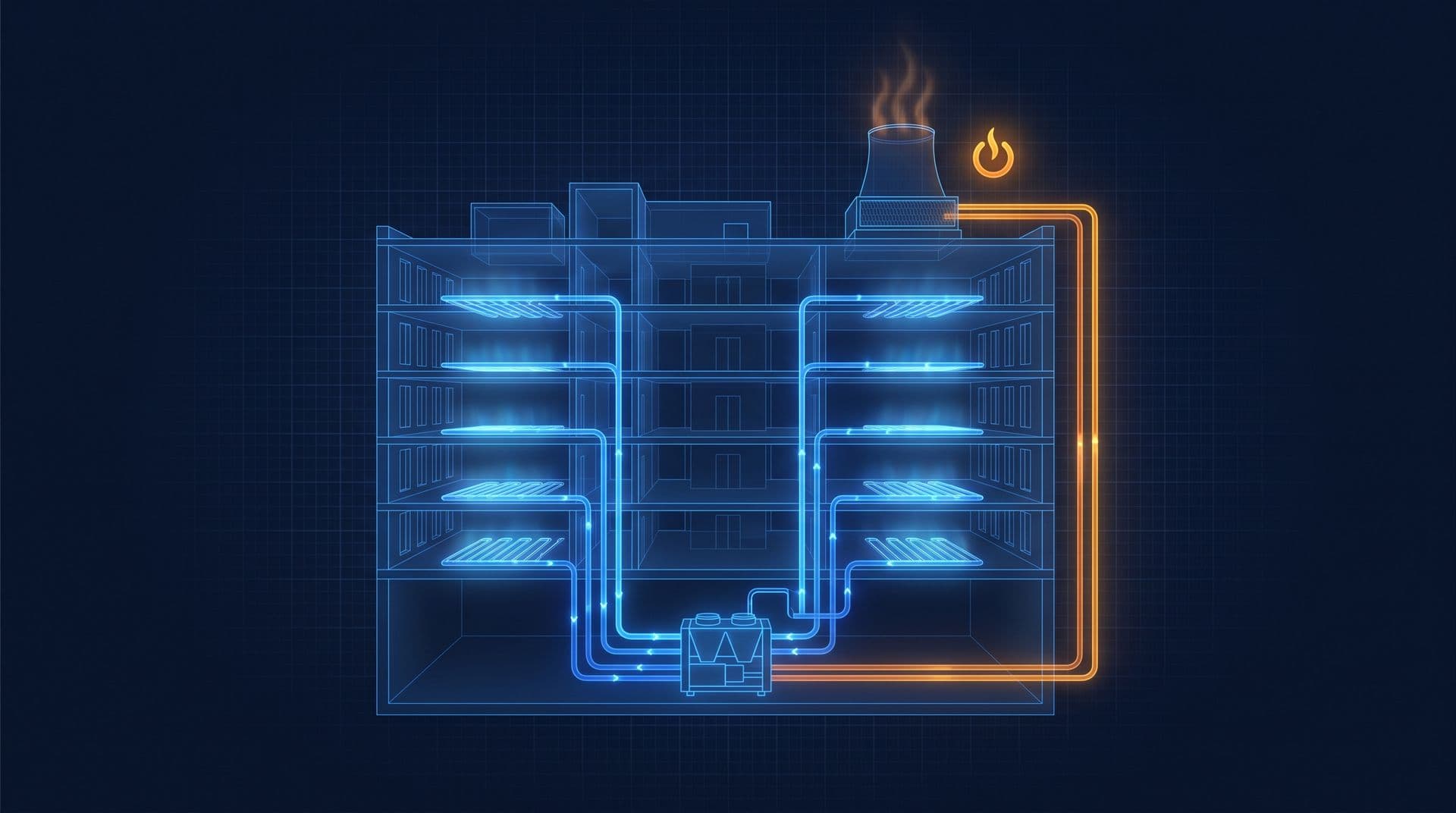
Part 8 of 20 in Cobler's Cooling Fundamentals course. New here? See the course page.
Part 7 ended at the top of the equipment ladder, where large buildings stop sending refrigerant to every room and send cold water instead. The office tower needs about 900 refrigeration tons (RT) of cooling on a hot afternoon. It does not use hundreds of split units: it makes cold water in one plant room and pumps that water to every floor.
So how does a chilled water system work? A machine called a chiller takes heat out of water, and pumps send that cold water through pipes to cooling coils around the building. The water picks up heat from the air, comes back warmer, and is cooled again. The heat that the chiller takes out of the water is then carried away and released outdoors, usually through a cooling tower on the roof.
This part builds that picture one loop at a time. It is the picture that most of the rest of the course hangs on. (If your building is cooled only by split units or VRF, like the shoplot, you can skim this part. Part 7 lists which later parts you need.)
A chiller moves heat along a chain
In Part 1 we saw that an air conditioner does not make cold. It moves heat from indoors to outdoors. A chiller does the same job, but in a large building the heat has a long way to travel: from an office on level 12 down to a plant room, and then up to the roof.
A useful comparison is a relay race. The "baton" is heat. Each loop of pipe picks up heat at one end and hands it to the next loop at the other end, until the heat is released outdoors. The plant has three loops: two carry water and one carries refrigerant sealed inside the chiller. We number them in the order the heat travels. Where the comparison stops working: in a relay race one runner finishes before the next starts, but in a chiller plant all three loops run at the same time, all day.
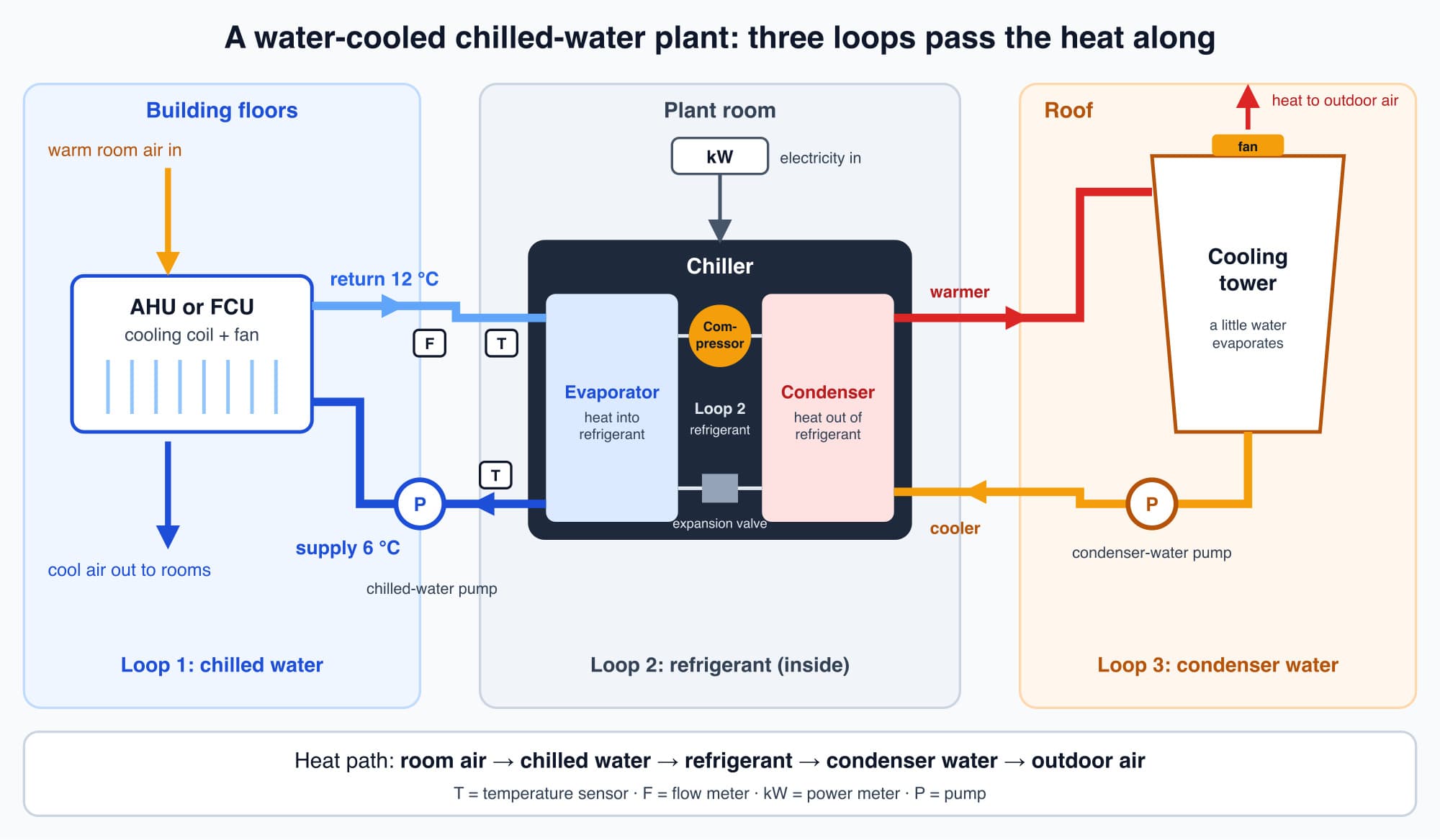
The three loops of a water-cooled plant, numbered in the order the heat travels. The T, F and kW tags mark where temperature, flow and electrical power are usually measured.
Loop 1, the chilled-water loop, collects heat from the building
This is the loop that reaches the building and does the comfort cooling.
The chiller cools water to about 6 °C. This is the chilled-water supply. Pumps push it through pipes to cooling coils all over the building. The coils sit inside air handling units (AHUs) and fan coil units (FCUs), the boxes that blow cool air into the rooms. Part 10 explains both. Room air blows across the cold coil, the air gives up its heat to the water, and cooler air goes on into the offices.
Because the water has taken in heat, it comes back warmer. This is the chilled-water return. The difference between the supply and return temperatures is called the delta-T ("delta" means "difference"). The office tower is designed for 6 °C supply and 12 °C return, a delta-T of 6 °C. This is a typical design example, not a rule: many plants supply at 6 to 7 °C with a delta-T of about 5 to 6 °C.
The temperature rise is the evidence that cooling was delivered, and delta-T is one of the most useful health signals a chilled-water plant has. Pumps, Valves and Flow (Part 9) shows how to turn flow and delta-T into kilowatts of cooling, and Low Delta-T Syndrome (Part 17) shows what goes wrong when delta-T is too small.
The warmer return water flows back to the chiller, is cooled to 6 °C again, and goes out again. That is the first hand-off: heat has moved from the building's air into the chilled water.
Loop 2, the refrigerant loop inside the chiller, takes the heat out of the water
The chiller now has a stream of warmer water coming back, and it must take the heat out of that water. It does this with the same refrigeration cycle we followed in The Refrigeration Cycle Explained Simply (Part 2), sealed inside the chiller and built much larger:
- In the chiller's evaporator, cold refrigerant takes in heat from the returning chilled water, cooling the water back to 6 °C. (Hand-off: heat moves from the water into the refrigerant.)
- The compressor, driven by a large electric motor, squeezes the refrigerant vapour. This raises its temperature above the temperature of the water or air it will release heat into.
- In the chiller's condenser, the hot refrigerant releases its heat and turns back into liquid. Then it passes through the expansion valve, cools, and returns to the evaporator.
The refrigerant loop is the link in the middle of the chain. It connects the building-side water at one end to the heat-release side at the other. What the condenser releases its heat into is what separates the two kinds of chiller (more on this below).
Loop 3, the condenser-water loop, carries the heat to the cooling tower
In a water-cooled chiller, the condenser hands its heat to a second water loop: the condenser-water loop.
Condenser pumps carry this water up to a cooling tower, usually on the roof. In the tower, the warm water is spread out in the outdoor air and a small part of it evaporates. Evaporation takes a lot of heat with it, so the rest of the water is cooled. The cooler water flows back to the chiller's condenser to collect more heat. How Does a Cooling Tower Work? (Part 12) explains the tower in detail.
So the full chain, from start to finish, is:
Room air → chilled water → refrigerant → condenser water → outdoor air.
That is four hand-offs. The heat that made an office feel stuffy ends up in the air above the roof. This is the whole job of a chilled-water plant.
Air-cooled or water-cooled: two ways to release the heat
Not every chiller has a condenser-water loop and a cooling tower. There are two kinds of chiller, and they differ only in how they release the heat at the last stage.
Air-cooled chillers have no second water loop. Fans blow outdoor air across the condenser, like a very large version of the outdoor unit of a split air conditioner. The heat goes straight from the refrigerant to the outdoor air. This is simpler: there is no tower, no condenser-water pumps and no tower water to treat. Air-cooled chillers are often seen on the roofs of mid-size buildings.
Water-cooled chillers use the condenser-water loop and cooling tower described above. They have more parts (a tower, extra pumps and water treatment), but large buildings accept this because water-cooled plants are usually more efficient. Evaporation in the tower can cool the condenser water below the outdoor air temperature, towards the wet-bulb temperature: the temperature a wet surface cools to as water evaporates from it, which is lower than the air temperature unless the air is saturated (Part 3 explains wet-bulb). Fans blowing air over a hot coil can only cool it towards the air temperature itself. A cooler condenser means the compressor does not have to squeeze the refrigerant as hard, so it draws less electricity for the same cooling.
That is why most large commercial buildings, such as malls, hospitals and large offices, use water-cooled plants, while smaller buildings often choose air-cooled chillers. The office tower is water-cooled, with three cooling towers on the roof. COP, EER and kW per Ton (Part 13) puts efficiency numbers on the comparison. For now, remember: the cooler the place the heat is released into, the less electricity the chiller needs.
Where the electricity goes
In many commercial buildings, the chiller's compressor is the single largest electrical load in the building, larger than any lift or lighting circuit. The compressor is driven by a large three-phase motor, and pushing a building's heat uphill to the outdoor temperature is hard work. Three-Phase Power Explained explains why large motors use three-phase supply, and How Electric Motors Work explains how they turn current into rotation.
The compressor is not the only motor in the plant. A chilled-water plant is a group of motors working together:
- The compressor: by far the largest single load.
- The chilled-water pumps: pushing water around the building loop.
- The condenser-water pumps: circulating water to the cooling tower (water-cooled plants only).
- The cooling-tower fans: drawing air through the tower to drive evaporation.
Together they are a large part of the bill. In the office tower, the chiller plant uses about 35% of the building's electricity, and whatever the plant motors draw during the month's highest-demand half-hour also counts towards its maximum demand charge. Part 14 follows the cooling plant through the bill. (Large motors running at light load also have a lower power factor, which raises the current they draw but not the kW on the bill. Part 13 explains why it does not change cooling efficiency, and Reactive Power Is Not Wasted Energy in our Electricity Fundamentals course explains the electrical side.)
The chiller and the building want different flows
One more feature explains a lot of the pipework you will see in a real plant room.
A chiller needs a steady flow of water through its evaporator. If the flow is too low, it cannot transfer heat properly and its safety controls can shut it down. But the building's need for chilled water changes all day. On a hot afternoon with a full office, cooling coils across the building are open wide and take a lot of water. At night, most coils are nearly closed.
So plants are designed to let the flow through the chillers differ from the flow through the building. Two common arrangements are:
- Primary-secondary pumping, which the office tower uses. One set of pumps (the primary pumps) keeps a steady flow through the chillers. A second set (the secondary pumps, fitted with variable speed drives) sends the building whatever flow it needs. A short pipe between the two circuits, called a decoupler, carries the difference.
- Variable-primary flow, a newer single-loop design in which variable-speed pumps change the flow through the chillers directly, within limits the chillers can safely accept.
You do not need the plumbing detail yet. Pumps, Valves and Flow (Part 9) explains it with numbers from the office tower.
Why a real plant has to be measured
Because the chiller flow and the building flow are allowed to differ, and because the plant spends most of its time at part load, you cannot judge its real performance from the nameplates. Real performance shows up only when you measure the plant as it runs: chilled-water flow, supply and return temperatures, and electrical power, recorded together over time. From these, you can work out the cooling delivered in kW and RT, and the electricity used per ton (kW/RT).
The office tower was designed for 0.85 kW/RT for the whole plant, but it measures 0.95 kW/RT. Only measurement shows that gap. Part 16 covers what to measure and where. These measurements describe how the loops are performing (flows, temperatures and power). They do not tell you the mechanical condition of a compressor or whether the refrigerant charge is correct; those checks belong to a qualified chiller technician.
Worth knowing: Chilled water coming back warmer is not a fault. If the water came back at the same temperature it left, it would have picked up no heat and done no useful work, but the pumps would still have used electricity to move it.
What comes next: moving the water
We have followed the heat through three loops. In each water loop, pumps and valves decide how much water goes where. The next part, Pumps, Valves and Flow, explains what a pump provides and how valves share the water between coils. It starts with the question: how much water has to flow to carry the cooling?
Check your understanding
- In a water-cooled chilled-water plant, list the four hand-offs of heat from a warm office to the outdoors. Room air to chilled water (at the AHU or FCU coil). Chilled water to refrigerant (in the chiller's evaporator). Refrigerant to condenser water (in the chiller's condenser). Condenser water to outdoor air (in the cooling tower, mainly by evaporation).
- Chilled water leaves the plant at 6 °C and comes back at 6 °C. What does that tell you? The water picked up no heat on its way around, so it delivered no cooling. The temperature rise between supply and return is the evidence that the water removed heat from the building. A delta-T of 0 °C means water is circulating, and using pump energy, without doing useful work.
Recap: A chilled-water plant moves heat along a chain of three loops. The chilled-water loop (about 6 °C supply, warmer return) collects heat from the building's air at AHU and FCU coils. The refrigerant loop inside the chiller takes that heat out of the water. In a water-cooled plant, the condenser-water loop carries the heat to a cooling tower, where evaporation releases it outdoors; an air-cooled chiller releases it straight to outdoor air with fans. Water-cooled plants are usually more efficient because evaporation gives a cooler place to release heat. The compressor is the largest motor in the plant, with pumps and tower fans alongside. The chiller and the building need different flows, so plants separate them, and real performance has to be measured.
Go deeper on video (optional)
This video shows the chilled-water loop and the condenser-water loop in a 3D model of an office building. It covers the three loops described above.
The Engineering Mindset uses a clear 3D model of an office building to walk through the chilled-water loop and the condenser-water loop working together to cool a whole building.
This is Part 8 of 20 in Cobler's Cooling Fundamentals course. Previous: Window, Split and VRF Air Conditioners: What's the Difference?. Next: Pumps, Valves and Flow: How Chilled Water Reaches Every Coil.
Cobler builds CobiNeural, a platform that shows a facility team its building's energy, water and indoor air data as live numbers across the whole site. To see how your building performs, talk to us.
FAQ
Frequently asked questions
Ask us about this topic
Something in this article you want to dig into — or a situation in your own building it doesn't quite cover? Send us your question. We don't run public comments; the team replies to you directly by email.