Blog
Reactive Power Is Not Wasted Energy
Utilities penalise reactive power, but it is not energy thrown away. Here is what your motors actually do with it, and where the real waste hides.
 Tan Kok XinElectricity Fundamentals
An optional side reading for Cobler's Electricity Fundamentals course. It goes with Part 11. See the course map.
Some TNB bills carry a power factor surcharge, and it is natural to assume it charges you for energy you wasted. It does not. Reactive power is energy that flows into the magnetic field of a motor or transformer and then flows back to the supply, 100 times a second on Malaysia's 50 Hz grid. It is not used up. What costs money is the extra current needed to carry it back and forth through the cables.
In the power triangle (Part 9) you met the three kinds of AC power: real power in kW, reactive power in kVAR and apparent power in kVA. This part explains what reactive power actually does, why equipment cannot work without it, and where the real cost is.
Some equipment needs a magnetic field to work
Many machines in a building work by magnetism. A motor needs a magnetic field to turn its shaft. A transformer needs a magnetic field in its iron core to pass energy from one coil to another. Pumps, fans, compressors, lifts and the air-conditioning plant are all driven by motors like these.
A coil of wire makes a magnetic field when current flows through it. On AC, the current reverses 100 times a second (see AC vs DC, Part 6), so the field has to be built up, taken down and built up again in the opposite direction, over and over. The current that does this job is called the magnetising current.
A motor needs its field before it can produce any turning force at all. Take the field away and the motor cannot turn. Transformers are the same: without the field in the core, no energy crosses from one coil to the other. We look inside these machines in How Transformers Work (Part 11) and How Electric Motors Work (Part 13). For now, you only need to know that they depend on a magnetic field that is built and rebuilt every cycle.
Reactive power flows into the field and back again
Building a magnetic field takes energy. The supply provides that energy, and the field stores it. When the field collapses a moment later, the stored energy flows back out to the supply.
On a 50 Hz supply, one full cycle takes 20 milliseconds (ms). Energy flows into the field for about 5 ms, then back to the supply for about 5 ms, and the pattern repeats. So the energy moves in and out 100 times a second, twice the supply frequency. Over each complete cycle, the amount that went in equals the amount that came back. The field uses no energy overall.
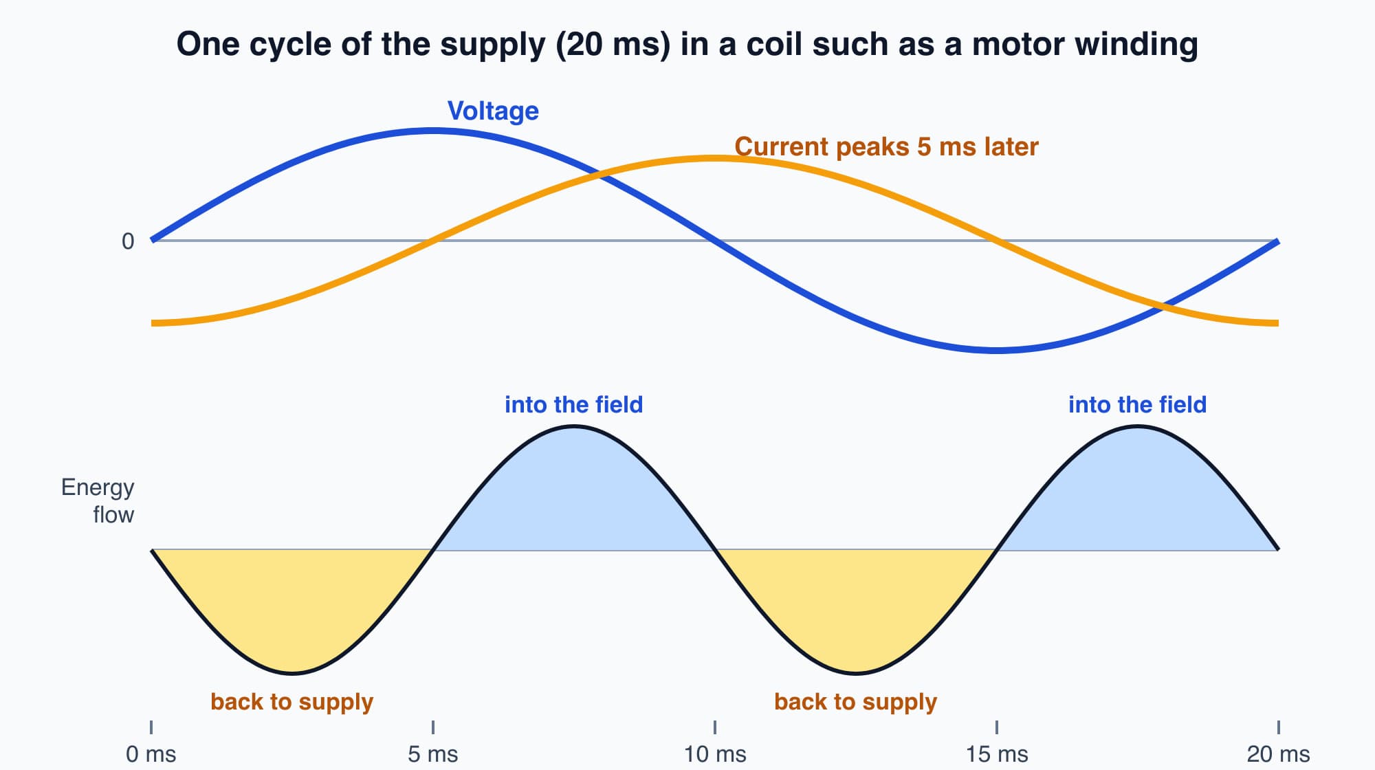
In a coil, the current peaks a quarter of a cycle after the voltage, so energy flows into the magnetic field and back out again twice every cycle.
This back-and-forth flow is what reactive power measures. Its unit is the kilovolt-ampere reactive (kVAR). It is different from real power, measured in kW, which leaves the circuit for good as heat, light or the turning of a shaft.
The current that carries reactive power does not rise and fall in step with the voltage. In a coil such as a motor winding, it peaks later than the voltage. Engineers call this a lagging current. The gap between the two peaks is the phase shift you met in Part 9.
(You may have heard a transformer hum. That sound comes from its iron core flexing slightly as it is magnetised, and it is also at 100 Hz. Part 11 explains it.)
The current that carries reactive power still heats the cables
If reactive energy comes back, why does anyone pay for it? Because the current that carries it still has to flow through real copper: your cables, your switchboard, and TNB's transformers and lines. A cable heats up whenever current flows through it, whether that current is doing useful work or just carrying energy back and forth.
Take a load that draws 4 A of working current (the part that does real work) and 3 A of reactive current. These two currents do not add up to 7 A, because they peak at different moments. They combine like the sides of a right-angled triangle, so the cable carries 5 A. This is the same triangle as the power triangle in Part 9.
The heating in a cable depends on the current multiplied by itself, which engineers write as I²R (current squared times the cable's resistance). So the heat is set by the full 5 A, not by the 4 A doing the work. With 5 A instead of 4 A, the cable heats about 1.6 times as much (5 × 5 = 25, against 4 × 4 = 16). That extra heat is the real waste: energy lost warming wires that carry current which does no work at the far end.
Reactive current also uses up equipment capacity
The second cost is capacity. Cables, transformers and switchboards are rated in kVA, apparent power, because their limit is set by the current and voltage they can carry. They cannot tell whether that current is doing useful work.
For example, a 1,000 kVA transformer serving a load at a power factor of 0.75 can deliver only 750 kW of real power instead of 1,000 kW. (Power factor, from Part 9, is the share of the apparent power that does real work.) The rest of its capacity carries about 660 kVAR of reactive power for the load. That is capacity which was built and paid for, and which now carries current back and forth instead of delivering useful power.
This is why TNB has a power factor surcharge. It recovers the cost of the extra current its network has to carry, and it encourages customers to keep that current low. In Peninsular Malaysia, TNB requires a power factor of at least 0.85 for supply below 132 kV, and at least 0.90 for supply at 132 kV and above. A site that falls below its threshold pays a surcharge. We explain how that charge works in the power factor surcharge explainer.
Why lightly loaded motors have poor power factor
A motor needs roughly the same magnetising current whether it is working hard or barely working. That current is typically 20 to 60 percent of the motor's full-load current, and it changes very little as the load on the shaft changes.
The working current is different: it grows and shrinks with the load. At full load, the working current is large, so the reactive share is small and an induction motor might run at a power factor of about 0.85. With no load on the shaft, the working current drops towards zero while the magnetising current stays. The power factor can then fall to about 0.15 to 0.30.
This is why oversized motors are a common cause of poor power factor at a site. For example, a 30 kW motor installed to do a 12 kW job spends its whole life lightly loaded. It draws close to its full magnetising current while doing a fraction of the work it could. Chillers, compressors, pumps, fans and older lighting ballasts all add the same lagging reactive current, and the more of them that run part-loaded, the lower the site's power factor.
Capacitors supply the reactive power close to the motor
You cannot remove the reactive power a motor needs, but you can change where it comes from. This is what power factor correction does.
A capacitor is a device that stores energy in an electric field, the way a coil stores it in a magnetic field. Its current peaks earlier than the voltage (a leading current), which is the opposite timing to a motor's lagging current. When a capacitor sits near the motor, the two swap energy between themselves: when the motor's field is collapsing, the capacitor takes the energy, and when the field is building again, the capacitor gives it back. The reactive current now flows only in the short loop between the capacitor and the motor. The motor still gets its field, but the cables upstream no longer carry that current.
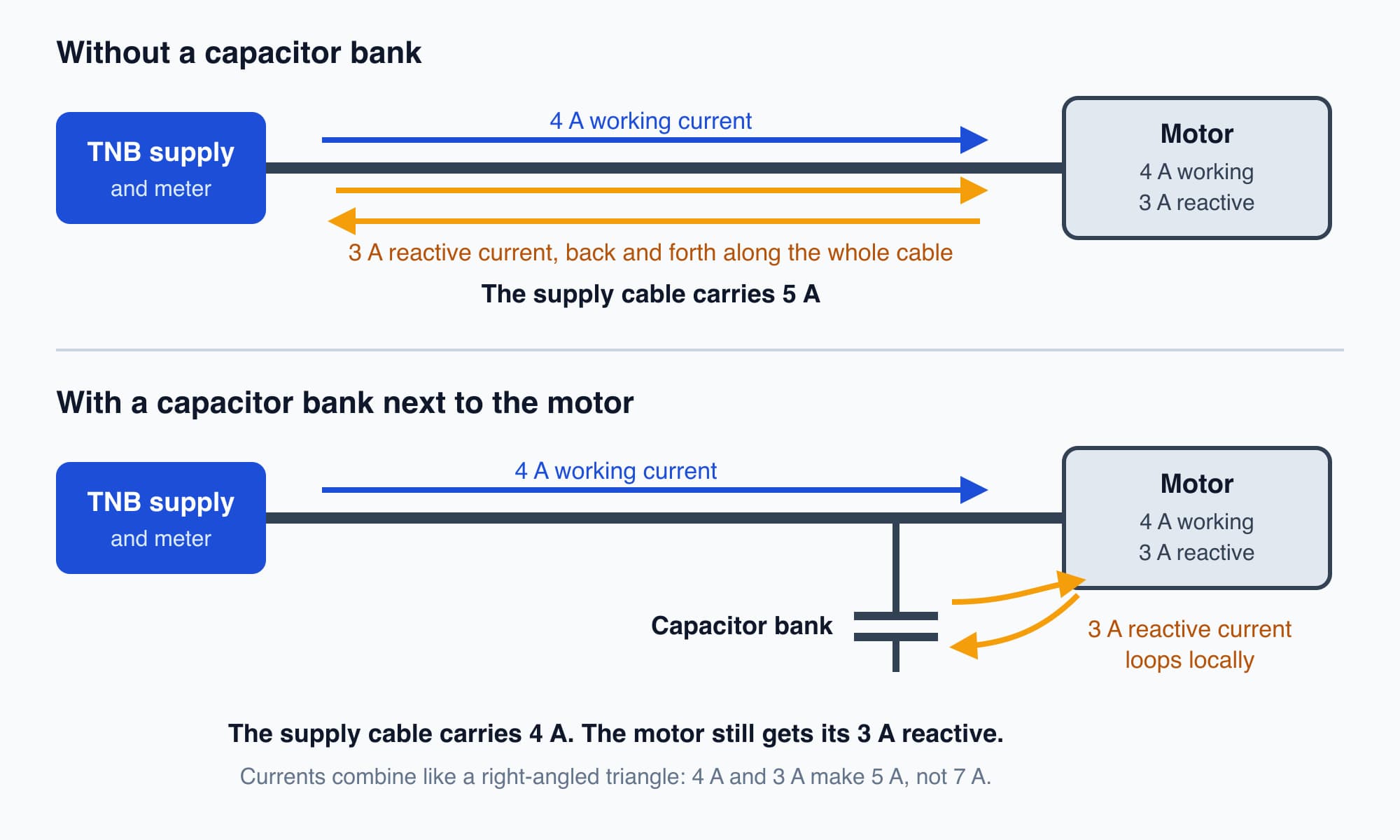
A capacitor bank next to the motor supplies its reactive current locally, so the cable back to the supply carries only the working current.
In our example, the supply cable now carries 4 A instead of 5 A. Here is what changes and what does not:
- Changes: the current in the cables and transformers upstream of the capacitor, the heat lost in them, the kVA the site draws, and the power factor seen at TNB's meter. Once the power factor is back above the threshold, the surcharge stops.
- Barely changes: the real power (kW) and energy (kWh) the motor uses. The motor does the same work, so it draws almost the same kW as before. On a medium-voltage tariff, where the maximum demand charge is per kW, better power factor therefore has little effect on that demand charge. The savings come from the surcharge, lower losses and freed capacity.
In practice, capacitor banks are usually installed at the main switchboard, where one bank corrects the power factor for the whole site. The same idea applies: the reactive current flows between the bank and the motors inside the building, instead of all the way from TNB. We cover how these banks are sized and controlled in Power Factor Correction: What Capacitor Banks Do (Part 21).
What comes next
This part mentioned transformers several times: they need a magnetic field too, and they are rated in kVA. The next part, How Transformers Work, explains how two coils on an iron core change 11,000 V into 400 V with no moving parts.
Check your understanding
- If reactive power is not used up, why does TNB charge for poor power factor? The current that carries reactive power still flows through cables and transformers. It heats them (the I²R loss) and uses up capacity that is rated in kVA. The surcharge recovers the cost of carrying that extra current.
- A site installs a capacitor bank and its power factor rises from 0.80 to 0.95. Does its kW maximum demand fall by the same proportion? No. The capacitors supply reactive power, not real power. The motors still do the same work, so the kW demand stays almost the same. What falls is the current, the kVA, the losses in the cables and any power factor surcharge.
Recap: Motors and transformers need a magnetic field. Energy flows into that field and back to the supply 100 times a second, and that back-and-forth flow is reactive power, measured in kVAR. It is not used up, but the current that carries it heats cables and uses capacity rated in kVA. A lightly loaded motor has poor power factor because its magnetising current stays while its working current shrinks. Capacitor banks supply the reactive current locally. That lowers current, losses and the surcharge, but it hardly changes kW or kWh.
Go deeper on video (optional)
This animation shows real and reactive power as moving pictures of voltage, current and energy flow, which can help after the section on reactive power flowing into the field and back. It is optional: you do not need it for the next part.
"Real vs Reactive Power" by Eugene Khutoryansky
This is an optional side reading for Cobler's Electricity Fundamentals course. Back to the course: Part 11: kW, kVA and kVAR: The Power Triangle.
Cobler builds CobiNeural, a platform that shows a facility team its building's electricity as live numbers: energy, demand and power quality across the whole site. To see how your building uses electricity, talk to us.
FAQ
Frequently asked questions
Ask us about this topic
Something in this article you want to dig into — or a situation in your own building it doesn't quite cover? Send us your question. We don't run public comments; the team replies to you directly by email.