Blog
Power Factor Correction: What Capacitor Banks Do
How a capacitor bank supplies a motor's reactive current locally, raises power factor toward 1, and removes TNB's surcharge, plus the silent failure that brings it back.
 Tan Kok XinUnderstanding Your Electricity Bill
Part 6 of 7 in Cobler's Understanding Your Electricity Bill course. New here? See the course page.
Part 5 left Aina with one line of the tower's bill still unexplained: a power factor of 0.92, and no surcharge. In the plant room next to the main switchboard there is a tall grey cabinet labelled POWER FACTOR CORRECTION, and she has been told to keep an eye on it. What does that cabinet do, what would a low power factor cost, and does the cabinet save money?
The cabinet holds a bank of capacitors. Power factor correction means supplying the reactive current that motors need from these capacitors, close to the motors, instead of drawing it through the TNB (Tenaga Nasional Berhad) network. That raises the site's power factor and keeps it above the level where TNB adds a surcharge to the bill. It changes the real power (kW) and energy (kWh) the site uses very little, so it does not lower the energy or maximum demand charges. This part explains the surcharge, how capacitor banks avoid it, and what they do not save.
Power factor in one paragraph
A site draws real power (kW), which does useful work such as turning a pump, and reactive power (kVAR), which builds the magnetic fields that motors and transformers need on every cycle. Together they make the apparent power (kVA), which sets how much current the cables and transformers carry. Power factor is real power divided by apparent power (kW ÷ kVA): at 1, all the current does useful work; at 0.80, only 80 kW of every 100 kVA does. Motors are the main cause of a low power factor. A typical induction motor runs at about 0.85 at full load, but its magnetising current barely changes as the load falls, so a lightly loaded or idling motor can drop to about 0.15 to 0.30. The Electricity Fundamentals lesson kW, kVA and kVAR: The Power Triangle explains all of this step by step, including why reactive power is needed and is not wasted energy.
TNB adds a surcharge when power factor falls below 0.85
TNB requires customers supplied below 132 kV, which covers nearly every commercial and industrial site at 11 kV or 33 kV, to keep their power factor at 0.85 or higher. At 132 kV and above, the threshold is 0.90 (TNB power factor page).
Below 132 kV, TNB's published formula works like this (TNB charges and penalties page, checked 23 September 2026):
- For every 0.01 that the power factor falls below 0.85, the surcharge is 1.5 percent.
- For every 0.01 below 0.75, the surcharge is 3 percent, added on top of the 1.5 percent steps between 0.85 and 0.75.
- The percentage is applied to the bill's energy, demand and AFA (Automatic Fuel Adjustment) charges. The retail charge and the KWTBB levy are not part of it.
Between 0.75 and 0.85, the surcharge is:
$$\text{Surcharge} = 1.5\% \times \text{Bill} \times \frac{0.85 - \text{PF}}{0.01}$$
Here "Bill" means the energy, demand and AFA charges added together, and PF is the month's power factor. At a power factor of 0.80, the site is five steps of 0.01 below 0.85, so the surcharge is 5 × 1.5% = 7.5% of those charges. At 0.70, it would be (10 × 1.5%) + (5 × 3%) = 30%.
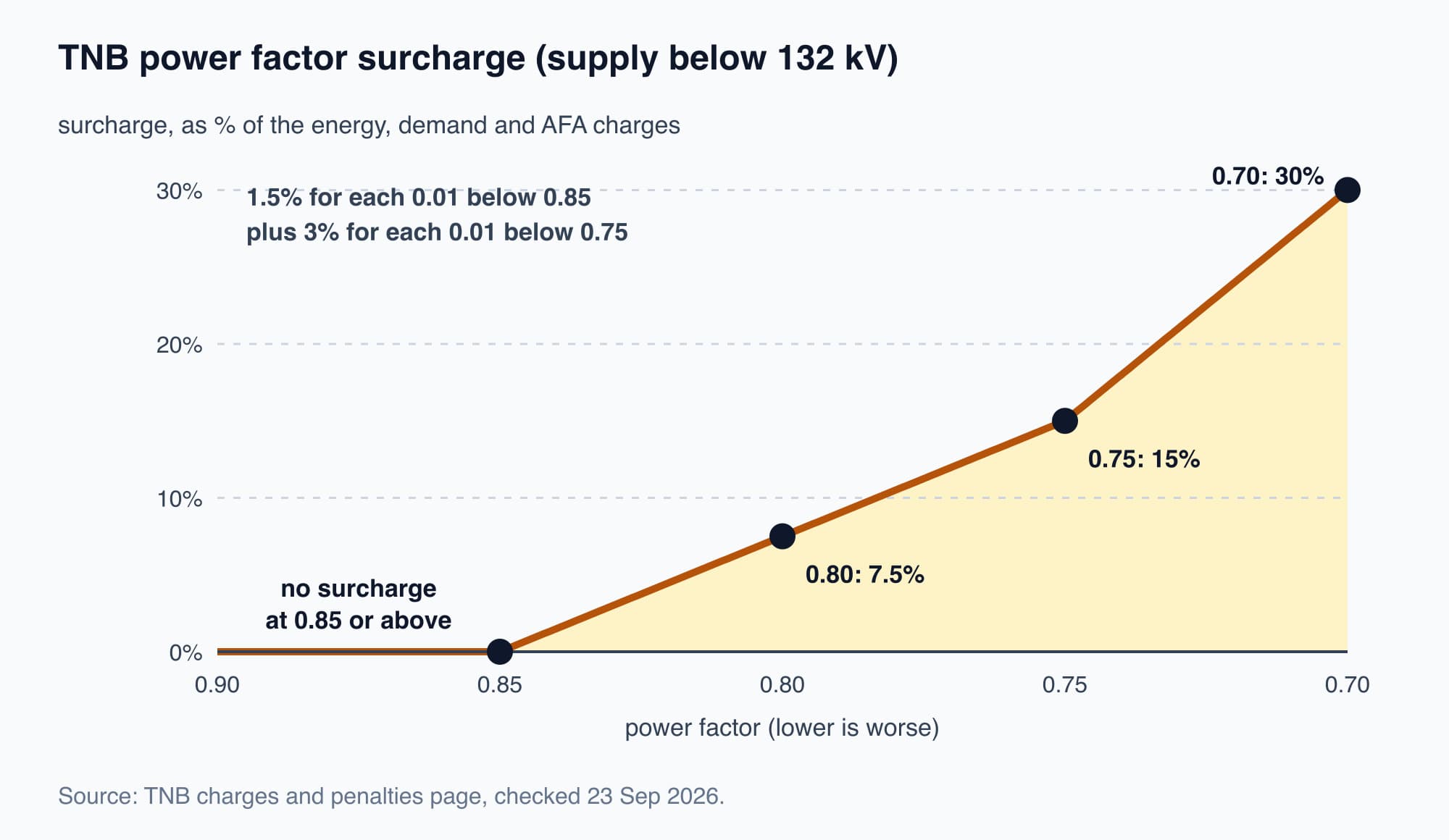
The surcharge starts below 0.85 and rises faster below 0.75. The percentage applies to the energy, demand and AFA charges.
TNB's published rule does not say how it applies to LV (low voltage) accounts, whose capacity and network charges are per kWh, so if you are on LV, like the shoplot, check your own bill.
What a low power factor would cost the tower
Aina's tower is on the MV (medium voltage) non-domestic General tariff. It normally runs at a power factor of about 0.92 with its automatic capacitor banks, so it pays no surcharge. Suppose the banks stopped working and the power factor fell to 0.80 in September 2026. From the bill in Part 3, its energy charge (RM149,150), demand charges (capacity RM47,088 plus network RM95,744) and AFA (RM18,350) add up to RM310,332. The surcharge would be 7.5% of that: RM23,274.90 in one month.
So the capacitor cabinet's main value on the bill is a charge that does not appear. As long as it keeps the tower above 0.85, the surcharge line stays empty.
What power factor correction does not change on the bill
Power factor correction does not lower the maximum demand (MD) charge. As Part 4 explained, under RP4 (the tariff structure in force since July 2025) the MV capacity and network charges are billed per kW of maximum demand. Capacitors reduce the kVA and the reactive power, not the kW that does the work. The tower's MD stays about 1,600 kW whether its power factor is 0.80 or 0.92. The kWh the building uses also stay about the same, so the energy and AFA lines do not change. The only energy saving is a small reduction in losses in the site's cables and transformers, because they carry less current.
What does change is the load on the site's own equipment:
Power factor | Real power (kW) | Reactive power (kVAR) | Apparent power (kVA) |
|---|---|---|---|
0.80 | 1,600 | 1,200 | 2,000 |
0.92 | 1,600 | about 682 | about 1,739 |
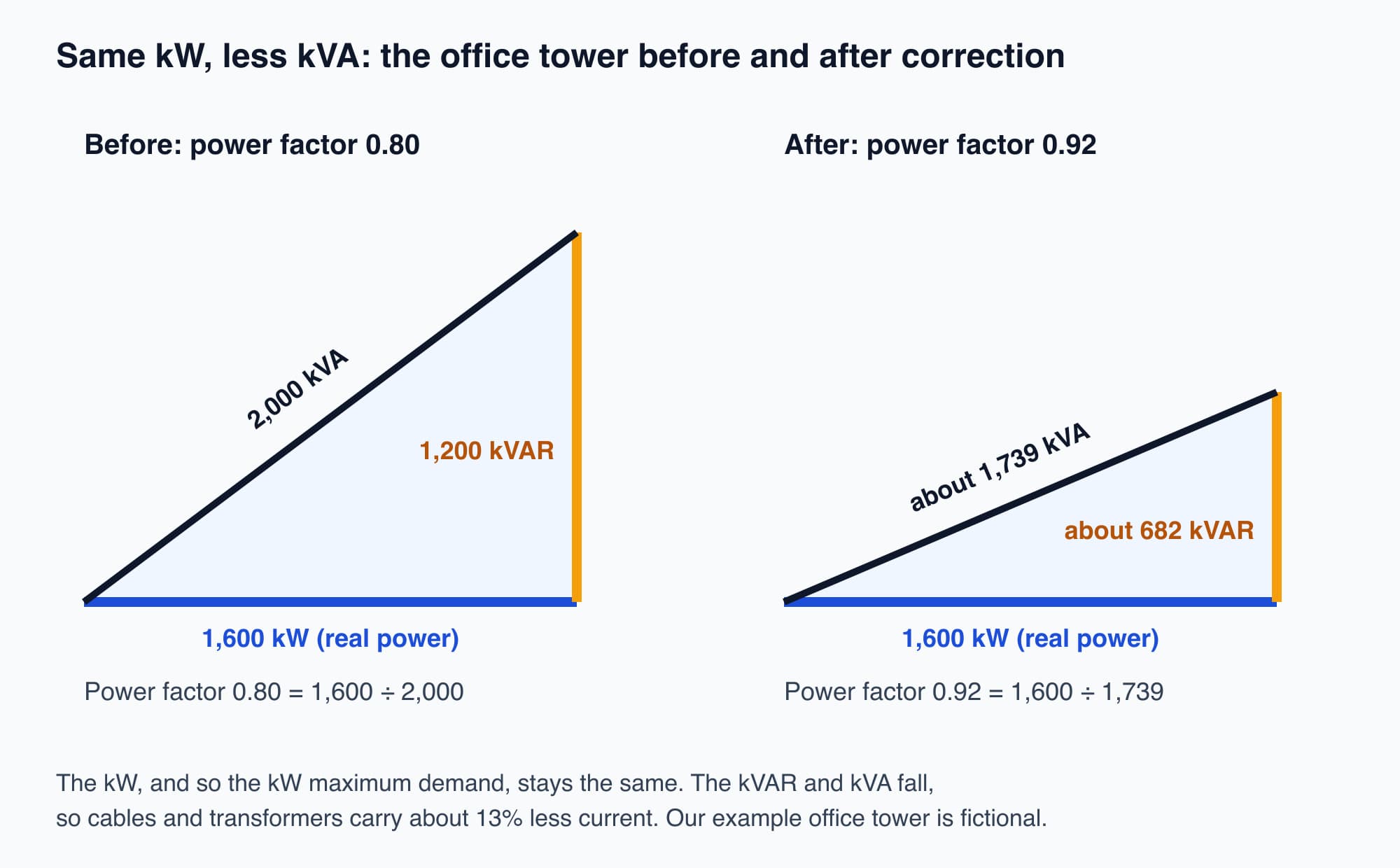
Correction shrinks the kVAR and kVA sides of the triangle. The kW side, which sets the maximum demand charge, stays the same.
At 0.92 the transformers and cables carry about 13 percent less current for the same work than at 0.80. For a sense of scale, a 1,000 kVA transformer at a power factor of 0.75 can deliver only 750 kW of useful power: a quarter of its capacity is taken up carrying reactive current. Raising the power factor frees that capacity for real load.
How a capacitor bank supplies the reactive current
A capacitor bank at the main switchboard supplies the motors' reactive current locally, so it no longer has to come through the TNB meter. A capacitor's current leads the voltage, while a motor winding's current lags, so the reactive energy moves back and forth between the capacitors and the motors on every cycle instead of travelling to and from the grid. The TNB meter then sees less kVA for the same kW, and the power factor rises towards 1. The power triangle lesson shows this with a diagram.
Why capacitor banks switch in steps
A site's reactive demand changes through the day, and too much correction causes its own problems. That is why real banks are automatic and switch in steps.
A building early in the morning, with one chiller and a few pumps running, needs a fraction of the reactive power it needs at 2pm with the whole plant running. A fixed block of capacitors sized for the afternoon would over-correct in the morning. Over-correction makes the power factor leading (the site's current leads the voltage) and raises the voltage on the site's switchboard. TNB publishes no surcharge for a leading power factor, but the voltage rise is a reason to avoid it. Power factor cannot go above 1.0, so the aim is not the highest possible figure but a controlled range, usually 0.95 to 0.98.
An automatic bank has several capacitor steps and a power factor regulator. The regulator measures the power factor continuously and switches steps in and out to follow the target as the load changes. This keeps the site above 0.85 without tipping it into leading power factor.
Why sites with VFDs need detuned capacitor banks
Where there are variable frequency drives (VFDs) and other electronic loads, a plain capacitor bank can amplify harmonics, so the bank is fitted with detuned reactors.
VFDs and other electronic loads draw harmonic currents at multiples of 50 Hz, such as the 5th at 250 Hz and the 7th at 350 Hz. (Electrical Harmonics, a side reading in our Electricity Fundamentals course, explains where they come from.) A capacitor bank and the inductance of the supply together form a circuit with a natural (resonant) frequency. If that frequency is close to a harmonic already on the busbar, the bank amplifies that harmonic instead of just correcting power factor. The capacitors overheat, protection trips and the bank fails early.
A detuned bank has a reactor (a coil) in series with each capacitor step, sized so the resonant frequency sits below the lowest harmonic present. A 7 percent reactor tunes the bank to 189 Hz, and a 14 percent reactor tunes it to 134 Hz. Both are well below the 5th harmonic at 250 Hz. Above its tuning frequency the bank behaves like a coil, so it cannot resonate with those harmonics. On most sites with VFDs, a detuned bank is the usual choice, and a harmonic measurement confirms which reactor size is needed.
Capacitor banks wear out without warning
A capacitor bank needs maintenance. Individual capacitor steps age and lose capacitance, and a step can drop out completely, for example when its fuse blows.
Worth knowing: When a capacitor step fails, nothing in the building changes. The regulator keeps switching the remaining steps, the cabinet still looks as if it is working, and the chillers and pumps run as before. The first sign is often a power factor surcharge on the TNB bill, a month or more after the failure.
This is why power factor is worth tracking continuously rather than checking once at commissioning. A monthly look at the power factor on the TNB bill is the minimum. An energy monitoring system that records power factor at the main switchboard shows a failing step as a downward trend soon after it starts, before it reaches the bill. For more worked cases of the surcharge, see our power factor surcharge article.
What comes next: Aina's report to the owner
Aina can now explain every line on the tower's bill. The power factor of 0.92 means no surcharge, and the capacitor cabinet is worth keeping in good order because a slip below 0.85 would add 1.5% of the energy, demand and AFA charges for every 0.01. Her last question is the one the owner asked at the start: "Why is it so high, and what can we do?" Part 7, Read and Reduce Your Electricity Bill, is a worked exercise in which she writes that report, using both example buildings' September 2026 bills and valuing three options.
Check your understanding
- A factory's power factor is 0.80. It installs a capacitor bank and the power factor rises to 0.95. What happens to its maximum demand charge, and why? Very little. Under RP4 the MV demand charges are billed per kW of maximum demand. The capacitors supply reactive power (kVAR) locally and reduce the kVA, but the kW the factory uses to do its work stays about the same. The saving comes from removing the power factor surcharge (7.5 percent of the energy, demand and AFA charges at 0.80) and from freeing transformer and cable capacity.
- Why is a real capacitor bank split into steps with a regulator, instead of one fixed block? The site's reactive demand changes through the day. A fixed block sized for the busiest time would over-correct at quiet times, making the power factor leading and raising the switchboard voltage. A regulator switches steps in and out to keep the power factor in a target range, usually 0.95 to 0.98.
Recap: Power factor is kW ÷ kVA, and lightly loaded motors pull it down. Below 132 kV, TNB adds a surcharge when power factor falls below 0.85: 1.5 percent of the energy, demand and AFA charges for each 0.01 below 0.85, and 3 percent for each 0.01 below 0.75. At 0.80, the tower would pay RM23,274.90 in September 2026. A capacitor bank supplies reactive current locally, so the grid carries less kVA and the power factor rises. Correction removes the surcharge and frees transformer and cable capacity, but barely changes kW, kWh or the per-kW demand charge. Real banks switch in steps, need detuned reactors where there are VFDs, and should be monitored because steps fail without visible signs.
This is Part 6 of 7 in Cobler's Understanding Your Electricity Bill course. Previous: Time-of-Use, Green Tariffs and Avoidable Penalties. Next: Capstone: Read and Reduce Your Electricity Bill.
Cobler builds CobiNeural, a platform that shows a facility team its building's energy, water and indoor air data as live numbers across the whole site. To see how your building performs, talk to us.
FAQ
Frequently asked questions
Ask us about this topic
Something in this article you want to dig into — or a situation in your own building it doesn't quite cover? Send us your question. We don't run public comments; the team replies to you directly by email.