Blog
Integrating Mixed-Vendor and Legacy Systems Into One BMS
How gateways, networks and protocol translation make a mixed-vendor, legacy building of chillers, meters and controllers behave as one coordinated BMS.
 Tan Kok XinBuilding Automation & BMS Fundamentals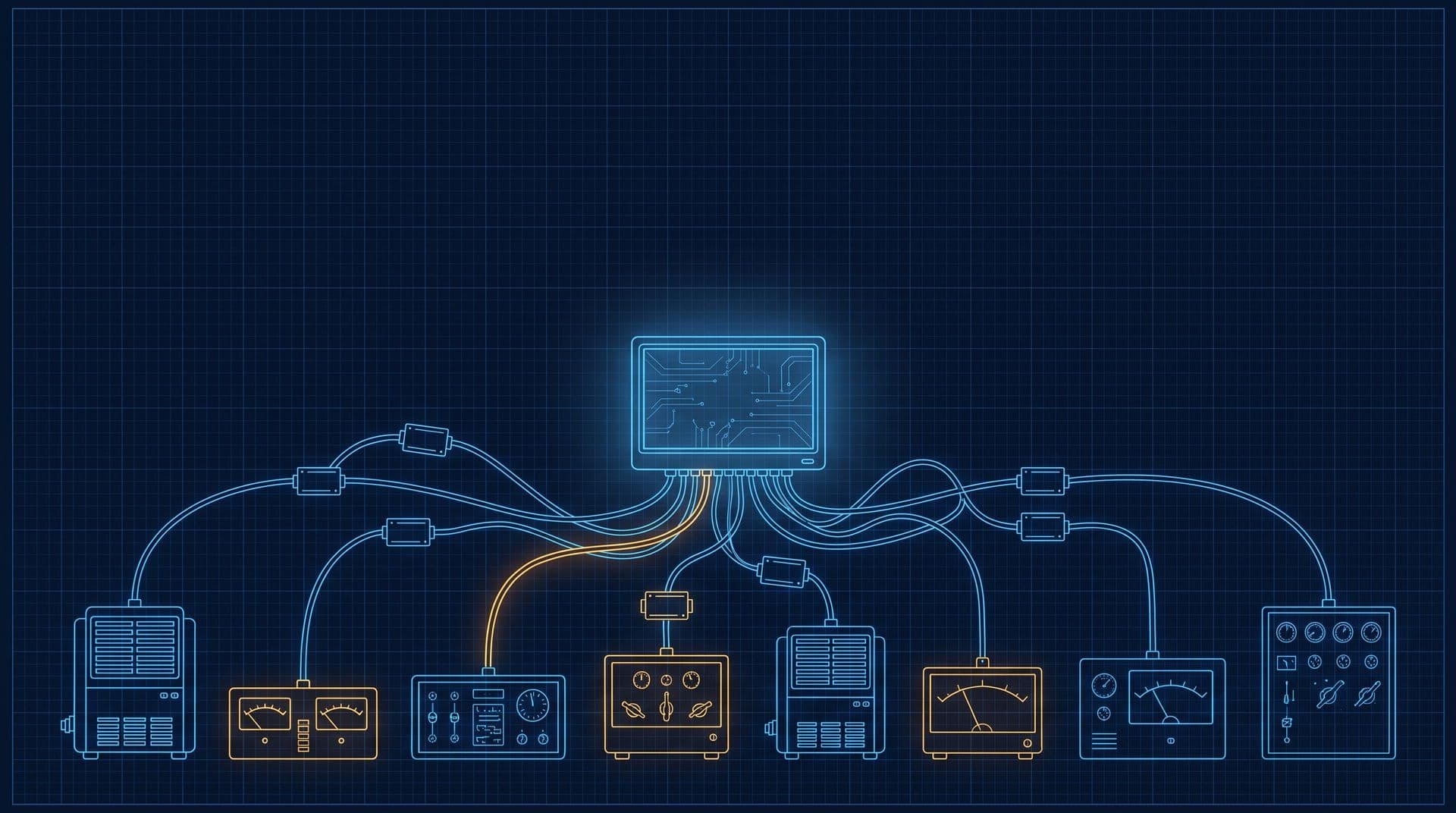
Part 10 of 16 in Cobler's Building Automation and BMS Fundamentals course. New here? See the course page.
Part 9 introduced BACnet, Modbus and the gateway between them, and ended on a harder question: how do you join equipment from different makers and different decades, some of it badly documented, into one BMS (building management system)? Most buildings are not built from one brand. The chillers arrive with the building, the energy meters come in a retrofit years later, the lighting panel comes from whoever won that tender, and new pumps bring yet another maker's controller.
Integrating mixed-vendor and legacy systems into one BMS means getting equipment from different makers and different years to report to, and take commands from, one supervisory system. It is done with three things: gateways that translate between protocols, a network designed to carry the data, and a point map that states exactly what every value means. This part walks through each one, with a full point-mapping example for the office tower's chillers.
Why a building ends up as a mix
A building collects equipment over decades. Each item was bought by a different project, installed by a different contractor and chosen to solve a different problem. That history causes three practical difficulties.
- Equipment installed years apart. A controller from 2010 and one from 2024 were designed to different assumptions. Even from the same maker, the older one may not support what the newer one expects.
- Different makers, different protocols. In Part 9 we met the two common languages: BACnet, built for whole-building systems, and Modbus, common inside individual equipment such as meters, drives and chillers. A mixed building speaks both, and often a proprietary language too, one that a manufacturer created for its own products and never fully published.
- Missing documentation. The contractor who commissioned the old lighting panel has moved on. The register map, the list that says what each Modbus register holds, was on a laptop that no longer exists. A large part of integration work is rediscovering what the equipment already reports but nobody wrote down.
So the equipment is not the problem. Each piece works well on its own. The problem is that nobody has introduced them to each other.
A gateway joins them, but only makes the data readable
Part 9 introduced the gateway: a device that reads one protocol on one side and offers the same values in another protocol on the other side. In the office tower, the BMS runs on BACnet and the three chillers speak Modbus. A gateway reads each chiller's registers and republishes the values as named BACnet points. The head-end, the server and screens where operators watch and command the building (Part 3), can then display, trend and alarm on the chillers like any other equipment.
A gateway does not make old equipment smarter. The chiller still runs its own internal control exactly as before. What the gateway does is make the chiller's data readable by the rest of the building. Whether that data is correct depends on how carefully the gateway was set up, which is what the next section covers.
A point-mapping example, one register at a time
Point mapping is the job of telling the gateway, for every value, where to find it and how to turn it into a correct, named point. The inputs are the manufacturer's register map and the building's naming rules. The output is a mapping table that the gateway follows.
Here is part of a mapping table for chiller CH-1 in the office tower. The register numbers, raw values and scaling are an illustration; the real ones come from the chiller manufacturer's register map.
Modbus register | Raw value | What the map says | Scaling | BACnet point on the BMS | Read or write |
|---|---|---|---|---|---|
40001 | 60 | Chilled water supply temperature, tenths of °C | × 0.1 | CH-1 CHW Supply Temp = 6.0 °C | Read |
40002 | 120 | Chilled water return temperature, tenths of °C | × 0.1 | CH-1 CHW Return Temp = 12.0 °C | Read |
40003 | 1 | Run status: 0 = off, 1 = running | none | CH-1 Status = Running | Read |
40004 | 72 | Percent of full load | none | CH-1 Load = 72% | Read |
40010 | 60 | Chilled water setpoint, tenths of °C | × 0.1 | CH-1 CHW Setpoint = 6.0 °C | Read and write |
The 6 °C supply and 12 °C return match the office tower's design temperatures. Now take the first row and follow it through the six checks a careful integrator makes.
1. Address. "40001" is a naming convention: the leading 4 means a holding register (the kind of register used for most readings and settings), and 0001 means the first one. On the wire, many devices number that same register as address 0. If the gateway and the register map count differently, every value shifts by one register, and the BMS shows the return temperature under the supply temperature's name. The fix is to test one known value first, before mapping the rest.
2. Data type. Each Modbus register holds a 16-bit whole number, which is a number from 0 to 65,535 (or from −32,768 to 32,767 if the map says it is "signed", meaning it can be negative). Larger values, such as a running energy total in kWh, are split across two registers. The two halves can be sent in either order, and if the gateway joins them the wrong way round, the BMS shows a huge, meaningless number. The register map says which data type each value uses.
3. Scaling and units. Modbus cannot send 6.0 directly, so the chiller sends 60 and the map says "tenths of a degree". The gateway multiplies by 0.1 and labels the result in °C. Leave out the scaling and the BMS shows 60 °C chilled water. Use the wrong factor and it shows 0.6 °C. The check is to compare each mapped value with a reading you trust, such as the chiller's own display or a calibrated thermometer on the pipe.
4. Timestamps and polling. Modbus devices only answer when asked (Part 9), so the gateway asks each chiller for its values on a repeating cycle. This is called polling. The value on the screen is only as fresh as the last successful answer. If the gateway polls every 30 seconds, a temperature on the BMS can be up to 30 seconds old, plus any delay further up the network. The trend log (Part 8) stamps each value with the time it was recorded, so the clocks on the gateway, controllers and head-end must agree. If they drift apart, events from different equipment appear in the wrong order.
5. Stale data. If a chiller stops answering, because of a loose cable or a controller restart, some gateways keep showing the last value they received. The BMS then shows a steady 6.0 °C that is no longer true. On a trend, it looks like a perfectly flat line. A good integration gives every gateway a communication failure status, raises an alarm when it trips, and marks the affected points as unreliable so that no sequence acts on them.
6. Read or write. Most mapped points should be read-only: the BMS watches them but cannot change anything. A few need to be writable, such as a chiller's enable command or its chilled water setpoint (the last row of the table), because the plant sequence in Part 12 changes them. Each writable point is a decision. Allow it only where the sequence needs it, limit the range the BMS may write, and record who can change it. The chiller's own safety controls stay in charge regardless of what the BMS writes.
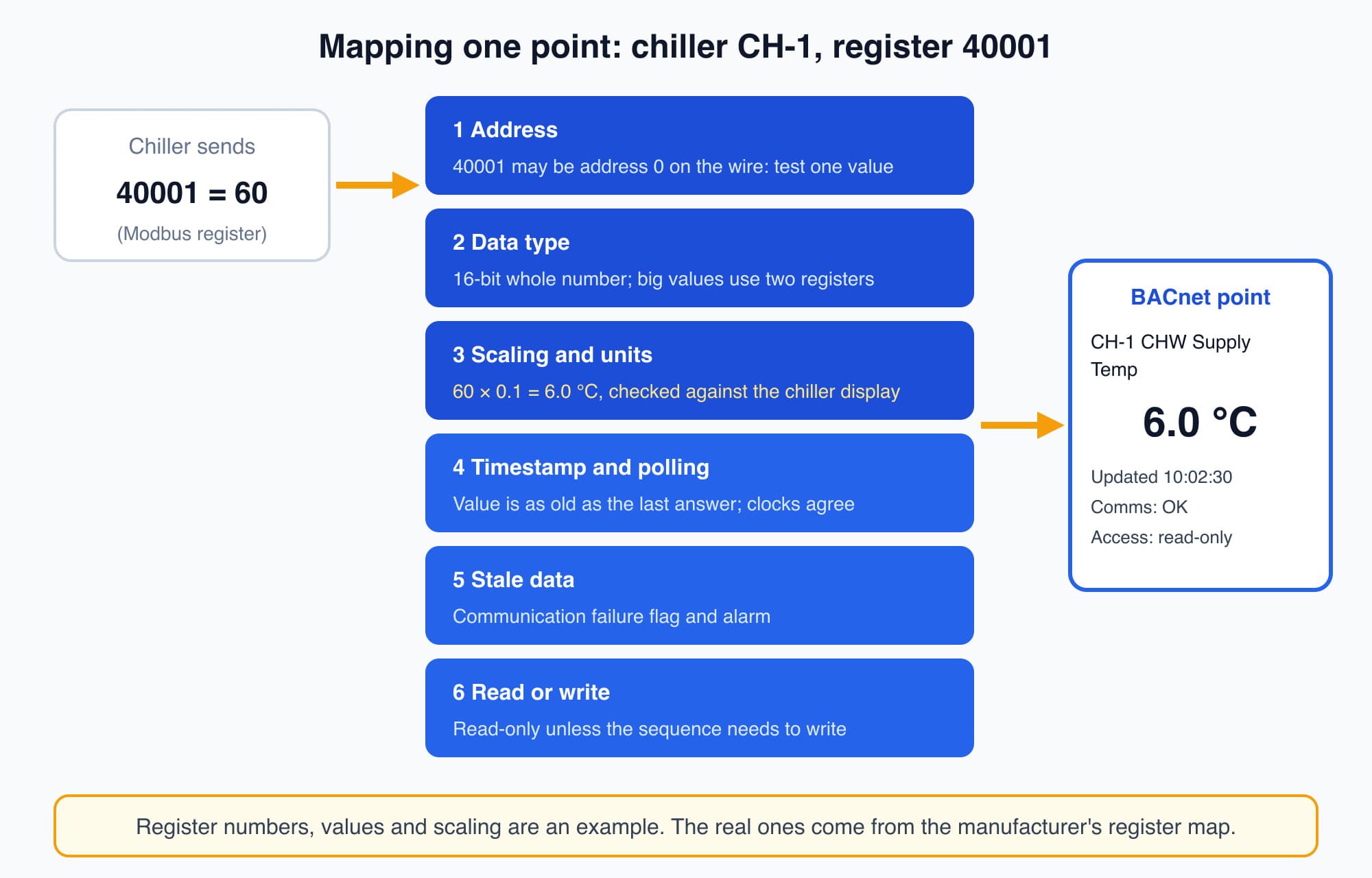
Every mapped point passes the same checks: the right register, the right data type, the right scaling and units, a fresh timestamp, a failure flag and a deliberate read or write decision.
Once the first row passes all six checks, the rest of the table goes faster, because the same mistakes tend to repeat across a whole register map.
The network carries the data, and it has to be designed
It is tempting to treat the network as a given: cables in the wall that either work or do not. In a real building, that assumption is where many integration projects go wrong. The network is a system that has to be designed, not assumed. A BMS network has two layers.
The field bus is the local wiring that links controllers and equipment in one area, such as a row of pumps or the room controllers on one floor. It is usually a simple twisted pair of wires running from device to device (a standard called RS-485). It is slow, because it only carries small, frequent messages over short distances. Both protocols have a field bus form: Modbus RTU and BACnet MS/TP.
The building backbone is the faster network, usually the same Ethernet and IP (Internet Protocol) networking used by office computers. It links the whole building and carries data up to the head-end. The IP forms of the two protocols are BACnet/IP and Modbus TCP. A useful comparison is roads: the field bus is a village road, and the backbone is the highway between towns.
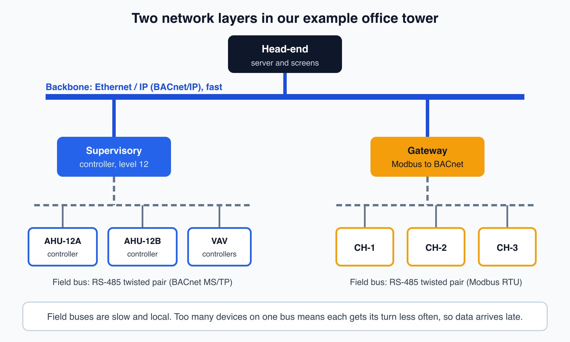
The field bus links devices in one area; the backbone links the whole building to the head-end, and gateways and supervisory controllers sit where the two meet.
A gateway or supervisory controller usually sits where the two layers meet. Designing the network means deciding how many devices share one field bus, how long the cable runs are, where the gateways sit and how the backbone is divided. If too many devices share one slow field bus, each one gets its turn less often and data arrives late. A head-end acting on late data is making decisions about conditions that have already changed. A network that was assumed rather than designed is a common reason a sound BMS feels slow and unreliable in use.
Bring a legacy system in without ripping it out
Almost every modernisation job meets the same situation. There is an old standalone system, such as a decade-old chiller controller or a lighting panel, that works well on its own but cannot be seen by the rest of the building. It has no BACnet and no obvious way in. Tearing it out is the expensive, disruptive and often unnecessary answer.
The better answer is to bring out the data it already has. Most legacy equipment offers something:
- A Modbus port. Add it to a gateway and map it, as in the point-mapping example.
- Dry contacts, simple switch contacts that open or close to show a state such as "running" or "fault". Wire them to spare digital inputs on a nearby BMS controller.
- An analogue output, such as a 4 to 20 mA signal carrying a temperature. Wire it to a spare analogue input.
These are the same AI and DI points you met in Part 3. Where the documentation is gone, the integrator has to work out what each signal means by careful testing, such as switching the equipment on and off and watching which contact changes.
The result is that the old chiller controller keeps running its own logic exactly as before, but the facility manager can now see its temperatures, status and alarms on the same screen as everything else.
Replacement still has its place: when equipment is at the end of its life, or when the old control logic itself is the problem. But "integrate first, replace only when justified" separates a thoughtful upgrade from a rip-and-replace sales pitch.
Get the integration records handed over
Part 9 explained how undocumented, closed systems tie an owner to one supplier. Integration work creates exactly the records that prevent this, so make sure they are handed over and kept by the owner, not only by the contractor:
- The points list: every point, its name, units and where it comes from.
- The register maps from each manufacturer.
- The gateway mapping tables and configuration files, like the table in the point-mapping example.
- A network drawing showing field buses, backbone, gateways and addresses.
Connecting the head-end and gateways to an IP network also changes who can reach the controls. A contractor can offer remote support without driving to site, but the same path, left unguarded, could let others in.
Worth knowing: Bringing out the data a legacy system already has, through a Modbus port, dry contacts or an analogue signal, usually costs a fraction of replacing it and causes far less disruption. The old controller keeps running its own logic; the building simply gains a view of it.
What comes next: who owns the BMS network
You can now see how a mixed building is joined into one BMS, and what makes each mapped point trustworthy. The next part, Who Owns the BMS Network? Access, Backups and Recovery, covers people, access and backups. It opens with this question: who is responsible for that network, who may log in and connect remotely, and what keeps running when it fails?
Check your understanding
- After a gateway is set up, the BMS shows CH-1's chilled water supply as 0.6 °C, but the chiller's own display shows 6.0 °C. What is the likely mistake? A scaling error. The register holds 60, and the gateway has been set to multiply by 0.01 instead of 0.1. Comparing a mapped value with a reading you trust, as in check 3, catches this before anyone relies on it.
- CH-1's supply temperature trend shows a perfectly flat 6.0 °C for three hours, including a period when the chiller was switched off. What should you suspect first? Stale data. The gateway has probably lost contact with the chiller and is still showing the last value it received. Check the gateway's communication status and alarm, as in check 5.
Recap: Buildings collect equipment from different makers and years, often with missing documentation. A gateway makes that equipment's data readable to one head-end, and point mapping makes it correct: the right register address, data type, scaling and units, fresh timestamps, a communication failure flag and a deliberate choice of read or write. The network has a slow field bus layer and a faster IP backbone, and it needs to be designed. Legacy equipment can usually be brought in through a Modbus port, dry contacts or analogue signals instead of being replaced. The owner should hold the points list, register maps, gateway files and network drawing.
Go deeper on video (optional)
This video recaps how the open BACnet standard lets equipment from many makers share one network, the idea from Part 9 that this part built on. It is optional.
Galco's Tech Tip explains how the open BACnet standard lets equipment from many different manufacturers speak one common language on a single building network.
This is Part 10 of 16 in Cobler's Building Automation and BMS Fundamentals course. Previous: BACnet vs Modbus: The Two Languages Building Equipment Speaks. Next: Who Owns the BMS Network? Access, Backups and Recovery.
Cobler builds CobiNeural, a platform that shows a facility team its building's energy, water and indoor air data as live numbers across the whole site. To see how your building performs, talk to us.
FAQ
Frequently asked questions
Ask us about this topic
Something in this article you want to dig into — or a situation in your own building it doesn't quite cover? Send us your question. We don't run public comments; the team replies to you directly by email.