Blog
How a BMS Optimises the Chiller Plant: Staging and Temperature Reset
How a BMS sequences chillers and resets chilled-water and condenser-water temperatures to cut energy, so the same plant runs efficiently or wastefully.
 Tan Kok XinBuilding Automation & BMS Fundamentals
Part 12 of 16 in Cobler's Building Automation and BMS Fundamentals course. New here? See the course page.
Part 11 finished the section on connecting and owning a BMS (building management system). The rest of the course applies it, starting with the question Part 11 ended on: how does the BMS decide how many chillers to run and how cold to make the water? On a hot weekday afternoon, every AHU (air handling unit) in the office tower is asking for cold water, and the chiller plant in the basement has to supply it. The plant (chillers, pumps and cooling towers) is the building's largest single electricity user, at about 35% of the building's electricity.
Chiller plant control comes down to three decisions the BMS makes again and again. Staging decides how many chillers run. Chilled water reset decides how cold the water leaving the chillers needs to be. Condenser water reset decides how cold the cooling towers should make the water that carries heat away. None of these needs new equipment; they are all settings and sequences in the BMS. Two identical plant rooms, with the same chillers, pumps and towers, can have very different electricity bills depending on how well these three are done.
This part assumes you know the main parts of a chilled water plant. If not, the Cooling Fundamentals course explains them; the first section gives a short refresher.
What the plant does, and how its efficiency is measured
A water-cooled chiller plant moves heat from the building to the outdoor air using two water loops and the chillers between them.
- The chiller makes cold water. Inside it, a compressor drives a refrigerant around a loop so that it absorbs heat from the building's water and rejects it into a second water loop.
- Chilled water pumps send the cold water out to the AHUs. In the office tower it leaves the chillers at 6 °C and comes back at 12 °C, having picked up heat from the air.
- Condenser water pumps carry the heat the chiller rejects up to the cooling towers on the roof.
- Cooling tower fans blow air through the falling condenser water. Some of the water evaporates, which cools the rest, and it flows back down to the chiller to collect more heat.
Two units describe how the plant performs. Cooling is measured in refrigeration tons (RT): 1 RT = 3.517 kW of cooling. Efficiency is measured in kW/RT: the electrical kilowatts the plant draws for each ton of cooling it delivers. Lower is better. An efficient plant runs at around 0.5 to 0.7 kW/RT; a poorly run one can go above 1.0 kW/RT for the same cooling. The office tower's plant was designed for 0.85 kW/RT and measures 0.95 kW/RT. (These figures depend on whether you measure the chillers alone or the whole plant with its pumps and towers; the office tower figures are for the whole plant. The Cooling course's lesson on COP, EER and kW/RT explains the difference.)
The office tower has three 500 RT centrifugal chillers, 1,500 RT installed in total. Two are "duty" chillers that share the load, and one is standby, so 1,000 RT is normally available. The peak cooling load is about 900 RT.
Everything the BMS commands here, the compressors, pumps and tower fans, is driven by three-phase electric motors, often through a variable speed drive (Part 2). For this part, what matters is which machines run and at what temperatures.
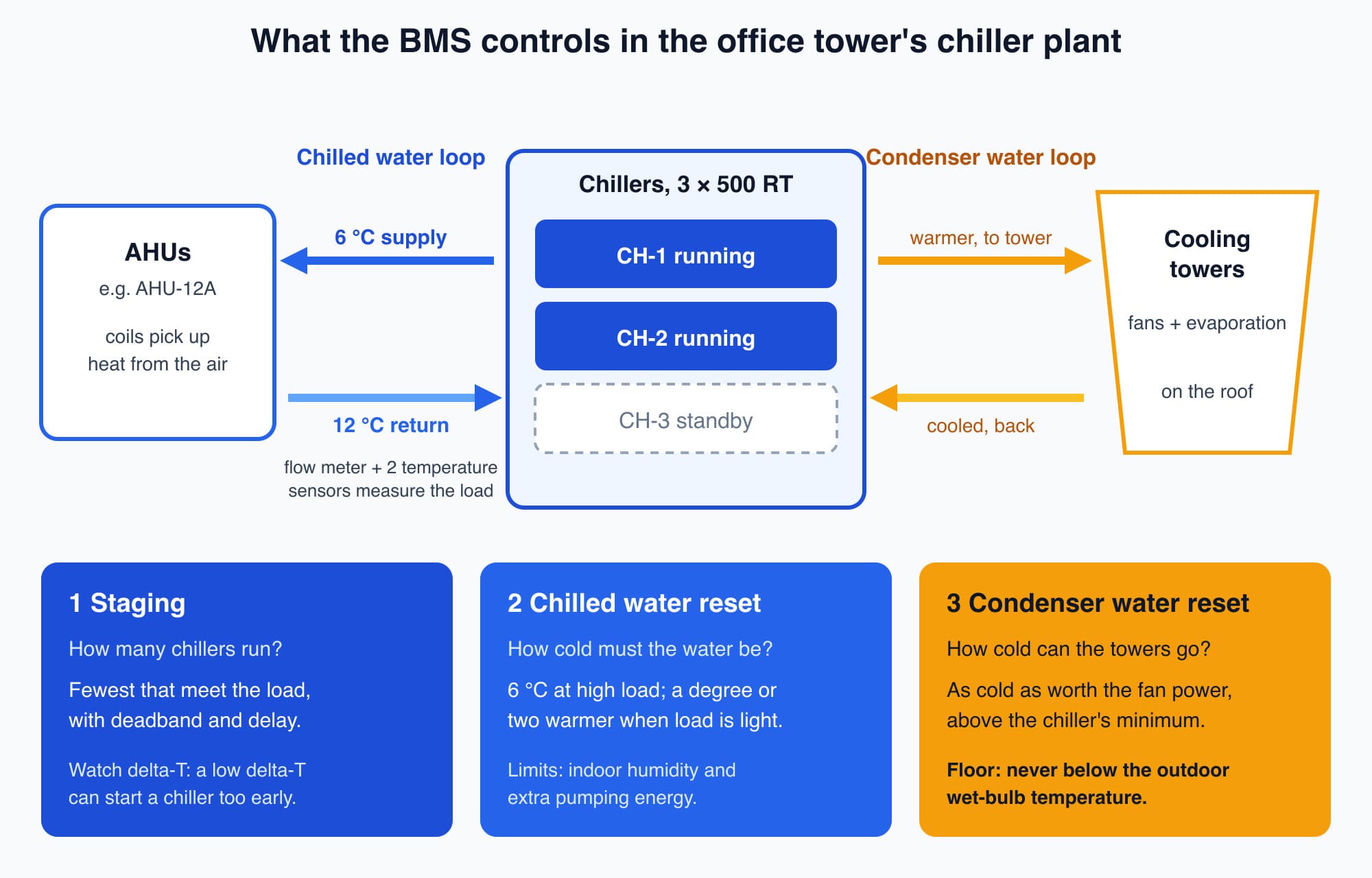
The BMS makes three decisions for the plant: how many chillers run, how cold the chilled water is, and how cold the towers make the condenser water.
The water carries the cooling, so the BMS watches flow and delta-T
Before the BMS can decide how many chillers to run, it needs to know the cooling load: how much heat the building is sending back to the plant right now. It works this out from the water.
The chilled water picks up heat in the AHU coils, so it comes back warmer than it left. The temperature rise is called the delta-T (ΔT, "delta" meaning difference). The cooling delivered depends on two things: how much water flows, and how much it warms up. For water:
cooling (kW) = flow (litres per second) × 4.19 × ΔT (°C)
The 4.19 is the energy, in kilojoules, needed to warm one litre (about one kilogram) of water by 1 °C. The Cooling course's lesson on pumps, valves and flow explains this formula, the pumps and the valves in more detail.
The BMS measures the load with a flow meter on the chilled water pipe and temperature sensors on the supply and return. Take the office tower at its peak of about 900 RT, which is about 3,165 kW of cooling. With the design ΔT of 6 °C (6 °C out, 12 °C back), the flow needed is:
3,165 ÷ (4.19 × 6) ≈ 126 litres per second.
Keep this number in mind. The section on low delta-T shows what happens when the ΔT is smaller than designed.
Staging runs the fewest chillers that can meet the load
On most hours, the building needs much less than the installed capacity. So the BMS has to decide which chillers to run, and how many.
It can be tempting to spread the load: run both duty chillers all day and let each carry half. On a morning when the load is 350 RT, that means two 500 RT chillers each running at 35% of capacity. One chiller could carry the same load at 70%. Running the second chiller adds overheads for no extra cooling. Each running chiller brings its own condenser water pump and its share of tower fans, and every machine has some losses just from running.
Staging (also called sequencing) is the part of the sequence that avoids this. The BMS measures the load as in the previous section and runs the fewest chillers that can meet it, each loaded in its efficient range. In the office tower on a typical weekday:
- Morning, load 350 RT. One chiller runs, at about 70% of its capacity.
- Afternoon, load rising towards 800 RT. Before the running chiller reaches its limit, the BMS stages up: it starts the pumps for the second chiller, proves flow, then starts the chiller. The two now share the load at about 80% each.
- Evening, load falling. When one chiller could carry the load again, the BMS stages down and stops the second chiller, so the remaining one stays well loaded.
Each stage-up and stage-down point has a deadband and a time delay. You met deadband in Part 4: a gap between the "start" and "stop" conditions. Together with a delay, it stops the plant switching a chiller on and off every few minutes as the load wobbles. The start-up order (pumps, proven flow, then chiller) is the interlock sequence from Part 6.
Which loading is "efficient" depends on the chiller. Many constant-speed chillers are most efficient at fairly high loads. Chillers with variable speed compressors can be very efficient at part load, especially when the condenser water is cool. The right stage-up and stage-down points therefore come from the chiller's performance data, not from a general rule.
A low delta-T can make the plant run more chillers than it needs
Staging decisions depend on the water's ΔT, and a problem on the air side can distort them. (Part 2 showed how even a drifted return water sensor distorts the calculated ΔT.) This problem is called low delta-T syndrome, and the Cooling course's lesson on low delta-T covers it in detail. Here is how it affects staging.
The office tower uses primary-secondary pumping. Each chiller has its own primary pump that pushes a fixed flow through it. Secondary pumps with variable speed drives then send water out to the building. A short pipe called the decoupler joins the two loops, so their flows can differ.
At the design ΔT of 6 °C, each 500 RT chiller needs about 70 litres per second through it. Two running chillers pass about 140 L/s.
Now suppose the AHU coils are dirty, or some control valves are stuck open, and the water comes back at 10 °C instead of 12 °C. The ΔT is now 4 °C. Same 900 RT load:
| Design ΔT (6 °C) | Low ΔT (4 °C) |
|---|---|---|
Flow the building needs at 900 RT | about 126 L/s | about 189 L/s |
Flow through two running chillers | about 140 L/s | about 140 L/s |
What happens | The chillers pass more than the building needs; the extra returns through the decoupler | The building needs about 49 L/s more than the chillers pass; warm return water flows back through the decoupler and mixes into the supply |
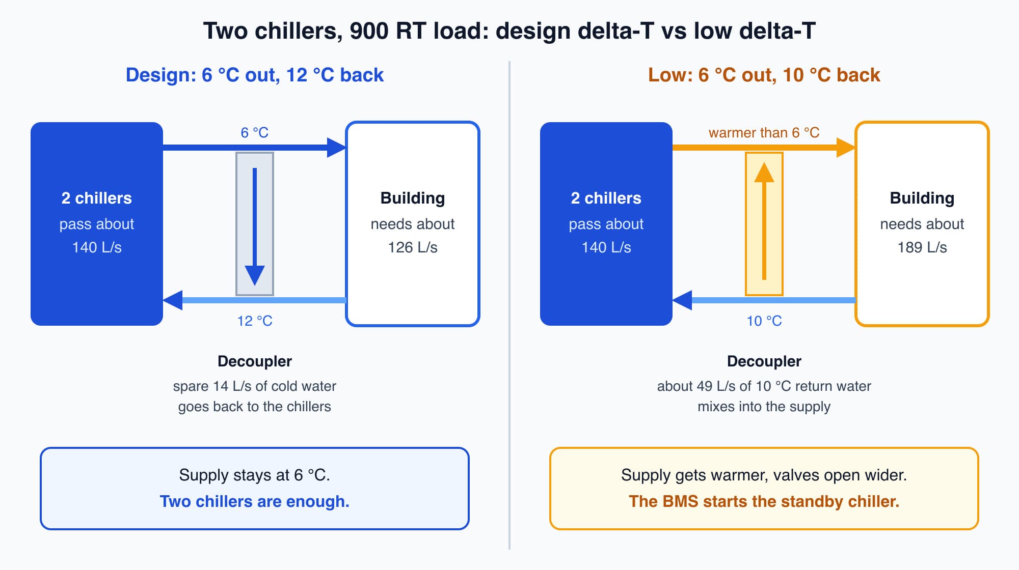
With a low delta-T, the building needs more water than the running chillers pass, so warm return water mixes into the supply through the decoupler.
In the low ΔT case, the water going to the building is warmer than 6 °C, because some of it has not been through a chiller. The AHUs open their valves further to compensate, which draws even more flow. The BMS sees rising supply temperature or high flow and starts the standby chiller, even though two chillers have 1,000 RT of capacity for a 900 RT load. The third chiller, its pumps and its tower fans all add energy, and the root cause is on the air side.
For the BMS, the lessons are practical: trend the chilled water ΔT, alarm when it stays low, and find out why before accepting that the plant "needs" another chiller.
Part load is where most operating hours are
You might expect a chiller plant to spend most of its time working hard. In practice it rarely does. Plants are sized for the hottest hour of the year, with full sun and a full building, and that hour is rare. For most hours, the plant runs at part load.
A typical building spends most of its operating hours around 50% to 75% load and very little time at full load. The industry's standard chiller rating reflects this, as the optional detail at the end of this part explains.
So part-load efficiency decides most of the plant's energy use, and part-load efficiency depends heavily on control. That is where the two resets come in.
Chilled water reset makes the water only as cold as the building needs
A chiller's compressor has to lift heat from the cold chilled water up to the warmer condenser water. The temperature gap between the two is called the lift. The bigger the lift, the harder the compressor works and the more power it draws. Reduce the lift, and the compressor uses less power for the same cooling.
Chilled water reset reduces the lift from the cold side. Instead of holding 6 °C all day, the BMS raises the chilled water setpoint when the building's cooling demand is light. On a mild or half-empty afternoon, the AHUs do not need the coldest possible water. The BMS lets the setpoint rise by a degree or two, and the compressors draw less power. When demand rises again, the reset brings the setpoint back down.
The BMS decides how far to reset by watching the AHUs. A common method looks at the chilled water valve positions. If even the busiest AHU's valve is only partly open, there is spare capacity, and the setpoint rises a little. If any valve is nearly fully open, that AHU is struggling, and the setpoint comes back down. This is the same feedback idea from Part 5, applied to the whole plant instead of one valve. The new setpoint is written to the chillers through the writable point you saw in Part 10's mapping table.
Two limits keep the reset safe in a Malaysian building:
- Humidity. The chilled water coil also removes moisture from the air. Warmer chilled water removes less of it, so indoor humidity can rise. The reset should have an upper limit and, where the AHUs measure it, should back off if space humidity climbs. Humidity is covered in the Cooling course.
- Pumping energy. Warmer water carries less cooling per litre, so the AHU valves open further and the secondary pumps move more water. Part of the chiller saving is spent on pump energy, so the reset should be tuned by watching total plant kW, not chiller kW alone.
If the BMS loses the AHU valve signals, for example during a network fault (Part 11), a well-written sequence returns to the design setpoint of 6 °C rather than guessing.
Condenser water reset makes the tower water as cold as the weather allows
The other side of the lift is the condenser water coming back from the cooling towers. The colder that water, the smaller the lift and the less power the compressor draws.
Condenser water reset runs the tower fans harder to bring the condenser water temperature down. This spends extra fan energy to save compressor energy. It is usually a good trade, because the compressor is by far the larger motor. But it has a limit: beyond some point, the extra fan power costs more than the compressor saves. A good sequence looks for the lowest total of chiller and tower fan power, and it respects the chiller manufacturer's minimum condenser water temperature.
There is also a physical floor, and in Malaysia it matters. A cooling tower cools water by evaporation, and evaporation is limited by the wet-bulb temperature: the temperature a wet surface reaches when air blows over it, which depends on how humid the air is. No amount of fan power can cool the condenser water below the wet-bulb temperature, and in practice the water leaves a few degrees above it. Malaysia's humid air keeps the wet-bulb temperature high, so condenser water reset in the tropics is about capturing every degree the humid air allows, within a narrower range than textbooks written for temperate climates assume.
The savings only exist while the sequences stay switched on
These three decisions add up to one point: the same plant can be efficient or wasteful with no change to its equipment, depending on whether staging and the two resets are switched on and tuned.
Many plants have these sequences in the BMS but not running. During a commissioning problem years ago, someone put the plant into a fixed manual mode, with all chillers on and setpoints at their coldest, and nobody switched the automation back on. Part 8 showed how overrides like this hide in a BMS. The hardware can do the job; the control is not doing it. That plant can run past 1.0 kW/RT indefinitely while an identical plant nearby holds 0.6.
How much is at stake depends mostly on where you start. Studies report meaningful plant-wide savings from optimised sequencing and reset, but the headline figures, often anywhere from 10% to 40%, depend heavily on how poor the starting point was. A plant that is already reasonably well run has less to gain; a plant stuck in manual mode has a lot. For plants that are already decent and add continuous monitoring and optimisation, a more modest figure of about 5% to 10% is typical.
For a sense of scale in the office tower: at the 900 RT peak, the measured 0.95 kW/RT means about 855 kW of plant power. At the design 0.85 kW/RT, it would be about 765 kW, a difference of about 90 kW at that moment. Closing that gap is mostly a matter of control: confirming the sequences are running, fixing a low ΔT, and trending kW/RT so any drift shows up.
Worth knowing: A cooling tower in a dry climate can produce much colder water than an identical tower in Malaysia. Towers cool by evaporation, which is limited by the wet-bulb temperature, and Malaysia's humid air keeps the wet-bulb high all year. That narrows the range condenser water reset can work in here.
Optional detail: AHRI (the Air-Conditioning, Heating, and Refrigeration Institute, a US standards body) publishes a part-load rating that combines a chiller's efficiency at 100%, 75%, 50% and 25% load into one figure. In that rating, full load gets only about 1% of the weight, and most of the weight is on the 50% to 75% band. This is a standard weighting for comparing chillers on paper, not a measured record of how many hours your building spends at each load. The Cooling course's lesson on chiller part-load efficiency explains the rating. For condenser water, a rule of thumb often quoted is that every 1 °F (about 0.6 °C) of warmer condenser water raises chiller power by roughly 1.0 to 1.5%. One refrigeration ton is also 12,000 BTU/h, the unit used in many chiller catalogues.
What comes next: the air side
The chiller plant makes the cold water. The AHUs and fan coil units then use it to cool and dry the air on each floor. The next part, How a BMS Runs the Air Side: VAV, Static Pressure Reset and Fresh Air, follows the chilled water into AHU-12A. It answers this question: once the chilled water reaches AHU-12A, how does the BMS control the airflow, the air temperature and the fresh air on the floor?
Check your understanding
- On a morning when the office tower's load is 350 RT, why should the BMS run one chiller rather than both duty chillers? One 500 RT chiller can carry 350 RT at about 70% of its capacity. Running two would leave each at about 35% and add a second set of condenser water pump, tower fan and running losses for no extra cooling. (The best loading for a particular chiller comes from its performance data.)
- Why can't condenser water reset bring the tower water down to, say, 20 °C in Kuala Lumpur? A cooling tower cools water by evaporation, which cannot cool it below the outdoor wet-bulb temperature, and in practice the water leaves a few degrees above that. Malaysia's humid air keeps the wet-bulb temperature high, so the reset can only capture the degrees the weather allows.
Recap: The chiller plant is the office tower's largest electricity user, and its efficiency is measured in kW/RT. The BMS measures the cooling load from chilled water flow and ΔT. Staging runs the fewest chillers that meet the load, with deadbands and delays to prevent short cycling. A low ΔT can make the plant start chillers it does not need, so ΔT should be trended and alarmed. Most operating hours are at part load, where control matters most. Chilled water reset raises the setpoint when demand is light, within humidity and pumping limits. Condenser water reset lowers the tower water temperature as far as the wet-bulb temperature and total fan power allow. None of this saves anything unless the sequences stay switched on.
Go deeper on video (optional)
This video walks through the main ways a chiller plant is made more efficient, including the staging and reset strategies covered above. It is optional.
The Engineering Mindset walks through the main ways a chiller plant is made more efficient, including plant sequencing plus chilled water and condenser-water temperature reset.
This is Part 12 of 16 in Cobler's Building Automation and BMS Fundamentals course. Previous: Who Owns the BMS Network? Access, Backups and Recovery. Next: How a BMS Runs the Air Side: VAV, Static Pressure Reset and Fresh Air.
Cobler builds CobiNeural, a platform that shows a facility team its building's energy, water and indoor air data as live numbers across the whole site. To see how your building performs, talk to us.
FAQ
Frequently asked questions
Ask us about this topic
Something in this article you want to dig into — or a situation in your own building it doesn't quite cover? Send us your question. We don't run public comments; the team replies to you directly by email.