Blog
Cable Size and Voltage Drop: Why Distance Matters
A power tool runs weak at the end of a long extension cord, and the cord comes back warm. That warmth is voltage drop, made touchable. Here is why distance changes everything, and how cable sizing answers just two questions: how many amps, and how far.
 Tan Kok XinBuilding Electrical Fundamentals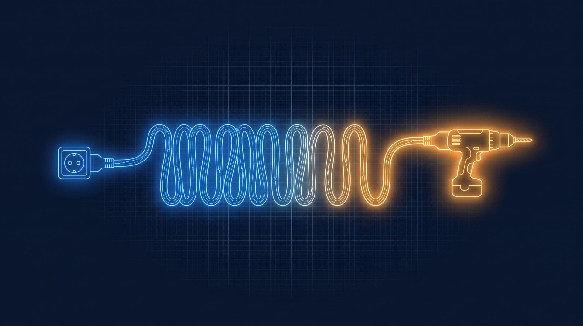
Part 5 of 11 in Cobler's Building Electrical Fundamentals course. New here? See the course page.
Part 4 showed that a breaker's rated current is chosen to protect the cable it feeds. So how is the cable chosen, and why do long cables need to be thicker?
Start with a small example. A cleaner runs a floor polisher from a long extension reel at the far end of a floor. At the end of the shift the reel is warm along its whole length, not just at the plug. The socket still gives 230 V, and the polisher works fine near the wall. The only thing that changed was the length of cable between the socket and the machine.
That warmth comes from voltage drop: voltage used up inside the cable itself, which turns into heat. Every cable in a building has the same effect, from the thick feeders that climb the riser to the thin final circuits in the ceiling. This part explains where voltage drop comes from, what sets its size, and how a designer chooses a cable that is thick enough for both the current and the distance.
You only need two ideas from Volts and Amps and What Is an Electric Circuit? in the Electricity Fundamentals course: Ohm's law, and the fact that current flowing through a resistance makes heat.
A cable has resistance, so it uses up some voltage
A cable is not a perfect pipe that delivers the full supply voltage to the far end. Copper has a small resistance, and every metre of cable adds a little more. So the cable acts as a resistance in series with the equipment at the end of it: the same current flows through both.
Ohm's law, V = I × R, tells us what happens next. V is voltage, I is current and R is resistance. When a current I flows through the cable's resistance R, a voltage I × R is used up inside the cable and never reaches the equipment. That lost voltage is the voltage drop. You would see it on a meter as the difference between the voltage at the start of the cable and the voltage at the far end while the load is running.
On a short run, the cable's resistance is so small that the drop is only a fraction of a volt. Over twenty or thirty metres, the small resistances add up. With a heavy current flowing, the equipment at the end now receives, for example, 230 V minus a few volts.
What the equipment does with less voltage depends on the type of load. An induction motor, such as a pump or fan motor, tends to draw more current when its voltage is low and it is still driving the same load. That extra current makes the drop in the cable larger still. (A simple heater does the opposite: with less voltage it draws a little less current and gives out less heat.)
The missing voltage becomes heat in the cable
The lost voltage does not disappear. Multiply the voltage drop by the current and you get watts: power turned into heat in the copper, spread along the length of the cable.
A kettle element does this on purpose. A cable that is too thin for its current and length does it by accident. The warm extension reel in the opening is the cleaner feeling energy that was meant for the polisher being lost as heat along the way. Keep this in mind for the section on current ratings: a cable's ability to lose heat sets how much current it may carry.
Worth knowing: Coiling makes the heating worse. A coiled cable cannot pass its heat to the surrounding air, so an extension reel used while still wound up runs hotter than the same cable laid out straight.
Two things set the voltage drop: length and thickness
Once you know the current, voltage drop depends on two properties of the cable.
The first is length. The drop is proportional to how far the current has to travel. Double the length and you double the drop. Two extension reels joined together give twice the drop of one.
The second is cross-section, the area of the copper, measured in square millimetres (mm²). The drop is inversely proportional to it. Double the area and you halve the resistance per metre, so you halve the drop. Going from a 2.5 mm² cable to a 4 mm² cable cuts the voltage drop by roughly 40% for the same run and current.
In a building, the current usually passes through more than one cable on its way to the equipment. In the office tower, power for a socket on level 20 leaves the main switchboard (MSB), climbs a riser feeder to the riser's sub-switchboard, reaches the floor distribution board (DB), and then travels along a final circuit to the socket. Each cable in that chain uses up some voltage, and the drops add up.
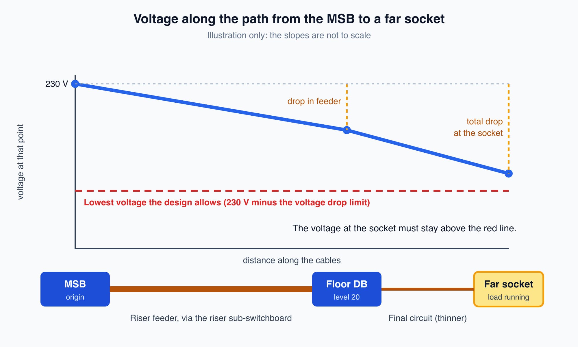
Each cable between the main switchboard and the far socket uses up part of the voltage, and together they must stay within the design's voltage drop limit.
Wiring guidance limits the voltage drop
Wiring guidance sets a limit on how much voltage the cables may use up between the origin of the installation and the equipment. Which limit applies depends on the type of building and how it is supplied, and the designer states it in the project's design. Here are the figures you are most likely to meet:
Guidance | Lighting | Other uses (power) |
|---|---|---|
Installation fed from a public low-voltage supply, such as a shoplot fed from a TNB substation down the street | 3% | 5% |
Installation fed from its own private supply, such as a building with its own transformer | 6% | 8% |
Suruhanjaya Tenaga (ST, the Energy Commission) residential wiring guidelines (homes) | 4% overall | 4% overall |
The office tower has its own transformers, so it falls in the second row; the shoplot, fed from TNB's substation, falls in the first. The percentages are measured from the origin of the installation to any load point. The optional detail at the end of this part gives the source of each row.
These are maximums, not targets. Many designers choose a tighter figure, especially for long runs or sensitive equipment, and the limit that applies to a particular building is the one in its design, set by the competent designer.
To get a feel for the size of these budgets: on a 230 V supply, 4% is about 9 volts. That small budget has to cover every cable between the origin and the socket. A long run uses it up quickly, which is why designers often choose a thicker cable for long runs than the current alone would need. It is cheaper to install thicker copper once than to deal with equipment at the far end of the building that runs poorly.
It is also why heavy loads get their own circuits. A water heater and, especially, an electric vehicle (EV) charger draw a large current for a long time. A 7 kW single-phase EV charger draws around 32 A for hours. Malaysian guidance requires it on a dedicated final circuit, and sizing typically starts at 6 mm² copper for that 32 A load (Suruhanjaya Tenaga Guidelines on Electric Vehicle Charging System, 2025). In a car park, the charger may also be far from its DB. The thicker cable carries the current without overheating and keeps the voltage drop within budget over that distance.
A cable's current rating depends on where it is installed
A cable's rated current assumes it can lose its heat to the surrounding air at a standard temperature. Installed conditions often make that harder. Several cables bundled together in one trunking warm each other. A Malaysian ceiling void can reach 45 °C. In those conditions the cable cannot lose its heat as easily, so it must carry less current.
Designers allow for this by derating: multiplying the rated current by factors below 1. Two common factors are:
- A grouping factor for cables installed together, often around 0.8 to 0.9 for a few cables. The more cables in a group, the lower the factor.
- An ambient temperature factor for hot surroundings. At 45 °C it is about 0.87 for cables with XLPE (cross-linked polyethylene) insulation and about 0.79 for cables with PVC insulation. PVC insulation is designed for a lower maximum conductor temperature (70 °C, against 90 °C for XLPE), so it has less room to cope with hot surroundings.
The factors multiply together. A cable rated 100 A with a grouping factor of 0.9 in a 45 °C ceiling can safely carry only about 78 A if it is XLPE (100 × 0.9 × 0.87), or about 71 A if it is PVC (100 × 0.9 × 0.79) (ECalPro, cable derating under IEC 60364). A cable that looks big enough on the drum can be too small once it is bundled with other cables in a hot roof space.
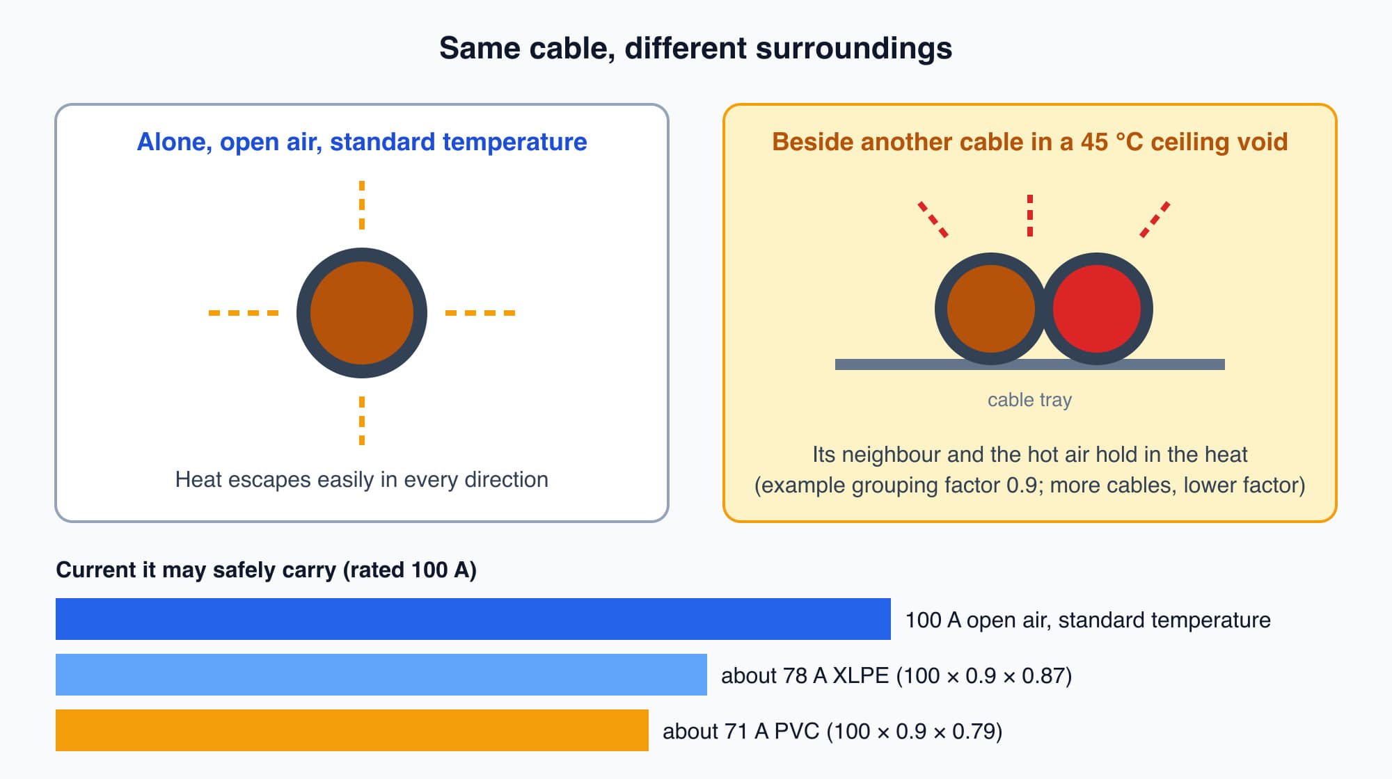
The same cable carries less current safely when it is grouped with other cables in a hot ceiling void, and PVC loses more of its rating than XLPE.
Choosing a cable size means answering four questions
Putting these steps together, a designer choosing a cable answers four questions:
- How much current will it carry? This sets the minimum copper area that can carry the load without overheating.
- Where and how is it installed? Grouping, surrounding temperature and the installation method reduce the current rating (see the current rating section above), so the cable may need to be larger.
- How far does it go? Length can force a larger cable still, because a cable that is thick enough for the heat can be too thin to keep the voltage drop within the limit (see the voltage drop limits above).
- Does it work with its protective device? The breaker or fuse must protect the cable against overload, and a fault at the far end must let enough current flow for the device to disconnect in the required time. Longer and thinner cables limit the fault current. Circuit Breaker Types (Part 4) explains how breakers are chosen.
The cable must pass all four. An electrician who fits a larger cable on a long run is answering question 3.
What voltage drop looks like in a whole building
The warm extension reel is a small version of a problem that also appears across a whole site. Long feeders to a far wing, DBs at the end of long cable runs, and circuits that were fine when the building opened but now feed loads nobody planned for can all have large voltage drops.
A facility team usually notices it in two ways:
- Complaints at the far end. Equipment at the end of the longest runs runs poorly or trips on hot afternoons when everything is loaded. Low voltage at the equipment is one possible cause. Voltage sags (brief dips in the supply voltage) are another, and the two can add together.
- Heat. A cable that is warm along its length under load is carrying a lot of current for its size. Heat concentrated at one spot in a board is different: it more often points to a loose or damaged connection. Both need a competent person to investigate, often with an infrared (thermal) camera scan.
Voltage drop can be measured directly. Compare the voltage at the origin with the voltage at the far end while the load is running, and the difference is the drop in volts. If a board has a meter that displays voltage, you can note its reading at a busy time and compare it with the reading at the main switchboard. Taking measurements inside a board is work for an authorised competent person: leave covers closed and report what you see. If the drop is too large, the fixes follow from what sets the voltage drop: a shorter route if the layout allows it, or thicker copper if it does not.
Optional detail: The first two rows of the table are the recommended maximums in the informative Annex G of IEC 60364-5-52, measured from the origin of the installation to any load point (Cableizer, IEC 60364-5-52 Annex G). The British wiring standard BS 7671, which shaped much Malaysian practice, uses the same 3% for lighting and 5% for power on a public supply (TotalSkills, BS 7671 voltage-drop guide). Malaysian homes are commonly held to a single 4% figure, following ST's Guidelines for Electrical Wiring in Residential Buildings, which follow MS IEC 60364.
What comes next
Cable sizing protects the cable from heat and the equipment from low voltage. Two more conductors run beside the live ones: neutral and protective earth. The next part, Neutral and Earth: Why They Stay Separate, asks: what does each one do, where may they meet, and why does an extra link between them cause problems?
Check your understanding
- A socket circuit on a far corner of a floor has twice the length of an otherwise identical circuit near the DB. With the same load current, how does its voltage drop compare? It is about twice as large. Voltage drop is proportional to length, because every metre of cable adds resistance and the same current flows through all of it.
- A cable is thick enough to carry its current in open air. Why might it still be too small once installed? Two reasons. Bundled with other cables or run through a hot ceiling void, it cannot lose heat as easily, so derating factors reduce the current it may carry. And on a long run, the voltage drop may exceed the design limit even when the cable does not overheat.
Recap: A cable has resistance, so by V = I × R some voltage is used up along it, and that lost voltage becomes heat. The drop is proportional to length and inversely proportional to the copper's cross-section, and the drops in each cable from the origin to the equipment add up. The limit that applies (for example 3% and 5% on a public supply, or 4% in ST's residential guidelines) is set in the building's design. Bundling and hot surroundings reduce a cable's current rating, and PVC loses more rating than XLPE. A designer sizes a cable for current, installation conditions, length and its protective device.
This is Part 5 of 11 in Cobler's Building Electrical Fundamentals course. Previous: Circuit Breaker Types: ACB, MCCB, MCB, RCCB, RCBO. Next: Neutral and Earth: Why They Stay Separate (TT and TN-S).
Cobler builds CobiNeural, a platform that shows a facility team its building's energy, water and indoor air data as live numbers across the whole site. To see how your building performs, talk to us.
FAQ
Frequently asked questions
Ask us about this topic
Something in this article you want to dig into — or a situation in your own building it doesn't quite cover? Send us your question. We don't run public comments; the team replies to you directly by email.