Cooling Plant Check: A Worked Example with Trend Data | Cobler
Blog
One Complaint, Three Loops: A Worked Cooling Plant Check
A worked exercise to finish the course. Trace a warm, humid complaint in our example office tower through the air, chilled water and condenser water loops using trend readings: delta-T, kW and RT of cooling, kW/RT and tower approach. Then a short version for a shoplot with split units and cassettes.
Tan Kok XinCooling Fundamentals
Part 20 of 20 in Cobler's Cooling Fundamentals course. New here?See the course page.
Part 19 was the last new idea in the course. This part puts the tools from all the earlier parts to work on one question: when a floor complains, which of the three loops is causing it, and how do you find out?
On a hot Thursday afternoon, the helpdesk in the office tower gets a call from level 12: "It's warm and sticky up here." The usual first response is to turn the thermostat down, or to blame the air handling unit (AHU) on that floor. But the air on level 12 is cooled by water from the chillers, and the chillers depend on water from the cooling towers on the roof. The cause could be in any of those three loops.
This final part is a worked cooling plant check. You follow one complaint through the air loop, the chilled water loop and the condenser water loop, using a small set of trend readings and the tools from this course. At the end there is a shorter version for the shoplot, which has split units and cassettes instead of a chiller plant.
How to use this cooling plant check
Each task gives you some information and asks a few questions. Try the questions first, with a calculator and a notepad. The Worked answer comes straight after each task so you can check your working.
As a reminder, the office tower has three 500 RT chillers (two on duty, one on standby), chilled water designed for 6 °C supply and 12 °C return, three cooling towers on the roof and a building management system (BMS). All the readings below are fictional but consistent with each other.
You need five tools from earlier parts:
Delta-T (ΔT) = return temperature − supply temperature. From Low Delta-T Syndrome (Part 17).
FAQ
Frequently asked questions
Ask us about this topic
Something in this article you want to dig into — or a situation in your own building it doesn't quite cover? Send us your question. We don't run public comments; the team replies to you directly by email.
kW/RT = electrical kW of the whole plant ÷ RT of cooling delivered. Lower is better. From COP, EER and kW per Ton (Part 13).
Approach = water temperature leaving the tower − outdoor wet-bulb temperature. From How Does a Cooling Tower Work? (Part 12), where a good approach was about 3 to 4 °C.
The trend readings
The facility engineer pulls the same set of readings from the BMS for two Thursdays at 3pm: last week, when nobody complained, and today. The relative humidity comes from a wall sensor on level 12. The outdoor wet-bulb temperature comes from the weather sensor on the roof. The plant's electrical input comes from the chiller plant's sub-meter, which covers the chillers, pumps and tower fans.
Reading at 3pm
Thu 10 Sep 2026 (no complaints)
Thu 17 Sep 2026 (complaint)
Air loop: level 12 east and AHU-12A
Room temperature (return air)
24.0 °C
26.5 °C
Room relative humidity
58%
72%
Supply air temperature (setpoint 14.0 °C)
14.0 °C
17.0 °C
Chilled water valve
70% open
100% open
Supply fan speed
75%
100%
Filter pressure drop (change at 250 Pa)
140 Pa
145 Pa
Chilled water loop: the plant
Chillers running
CH-1 and CH-2
CH-1 and CH-2
Chilled water supply (setpoint 6.0 °C)
6.0 °C
8.0 °C
Chilled water return
11.0 °C
12.5 °C
Chilled water flow through the running chillers
140 L/s
140 L/s
Whole plant electrical input
790 kW
800 kW
Condenser water loop: the towers
Outdoor wet-bulb temperature
26.5 °C
27.0 °C
Condenser water leaving the towers
30.0 °C
33.5 °C
Tower fans CT-1 and CT-2
Both running
CT-1 running; CT-2 stopped (BMS command: run)
The helpdesk log also shows that, by 3:30pm on 17 September, levels 14 and 17 have called about warm, humid offices too.
{{media:443}}
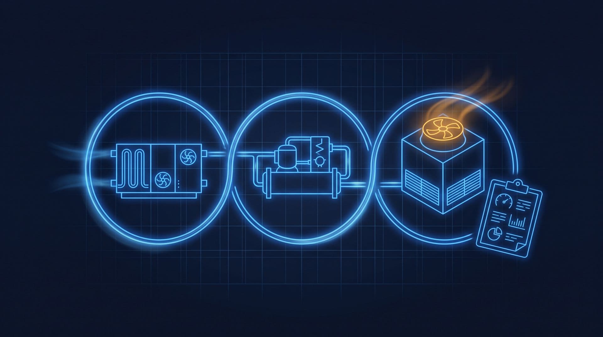
The complaint-day readings placed on the three loops: air, chilled water and condenser water.
Task 1: Start where the complaint is: the air loop
Look at the air loop rows for AHU-12A.
Are the room conditions outside the comfort ranges in the Industry Code of Practice on Indoor Air Quality 2010 (ICOP IAQ 2010) from Part 4: 23 to 26 °C and 40 to 70% relative humidity?
Is AHU-12A trying to cool harder, or has it given up?
Could a dirty filter explain the complaint?
Why is the room humid as well as warm?
Worked answer
Yes. The room is at 26.5 °C and 72% relative humidity, just above both upper limits. On the normal day it was 24.0 °C and 58%, well inside them.
It is trying as hard as it can. Its chilled water valve is 100% open and its supply fan is at 100% speed. Even so, its supply air is 17.0 °C, three degrees warmer than its 14.0 °C setpoint. The control loop from Part 19 is asking for more cooling and not getting it.
No. The filter pressure drop is 145 Pa, almost the same as last week and well below the 250 Pa change point. Air is getting through the filter normally.
Moisture is removed when water vapour condenses on a coil colder than the air's dew point (Part 3). If the coil is warmer than usual, for example because the water reaching it is warmer, less moisture condenses, so the air leaving the AHU is both warmer and wetter.
Conclusion: AHU-12A is working at full output and still cannot reach its setpoint. It looks like a victim, not the cause. The next question is whether the water reaching its coil is as cold as it should be. The calls from levels 14 and 17 point the same way: a problem at one AHU would not usually affect three floors.
Task 2: Follow the water back: the chilled water loop
Now look at the chilled water rows.
What is the chilled water delta-T on each day?
How much cooling did the plant deliver on each day, in kW and in RT?
Is this low delta-T syndrome?
What is the most important change between the two days?
Worked answer
Normal day: 11.0 − 6.0 = 5.0 °C. Complaint day: 12.5 − 8.0 = 4.5 °C.
Normal day: 140 × 4.19 × 5.0 = 2,933 kW, and 2,933 ÷ 3.517 = about 834 RT. Complaint day: 140 × 4.19 × 4.5 = 2,639.7 kW, and 2,639.7 ÷ 3.517 = about 751 RT.
Not mainly. The delta-T fell a little, from 5.0 to 4.5 °C, but the flow was the same on both days and the plant did not start an extra chiller. Low delta-T is not what changed. (The normal-day 5.0 °C is itself below the 6 °C design, which is worth a separate look later using Part 17. It did not cause today's complaint.)
The chilled water supply is 8.0 °C instead of its 6.0 °C setpoint. The chillers are not making the water as cold as they are told to. So every AHU in the building gets warmer water, which explains why several floors are complaining.
The two running chillers are rated 500 RT each, 1,000 RT together. On the complaint day they delivered only about 751 RT, less than the 834 RT of the normal day, although the building was warmer and was asking for more. Something is holding the chillers back.
Task 3: How efficiently is the plant working?
Work out the plant's kW/RT on each day.
How much more electricity is the plant using for each RT on the complaint day?
How do both figures compare with the plant's design target of 0.85 kW/RT?
Worked answer
Normal day: 790 ÷ 834 = about 0.95 kW/RT. Complaint day: 800 ÷ 751 = about 1.07 kW/RT. (Using the unrounded RT: 790 ÷ 833.95 = 0.947 and 800 ÷ 750.55 = 1.066.)
1.066 ÷ 0.947 is about 1.13, so the plant is using about 13% more electricity for each RT of cooling, while delivering less cooling.
Both are worse than the 0.85 kW/RT design target. The normal-day 0.95 kW/RT is the office tower's usual measured figure, so there is room to improve on an ordinary day. Today's problem has made it worse again.
The plant's electrical input barely changed (790 to 800 kW), but its cooling output fell. The chillers are working as hard as before and achieving less. That is what happens when a chiller has to push its heat out against hotter condenser water, which leads to the third loop.
Task 4: The third loop: the cooling towers
Now look at the condenser water rows.
What is the tower approach on each day?
Did the weather change enough to explain the difference?
What else in the table explains it?
Why does hotter condenser water hold the chillers back?
Worked answer
Normal day: 30.0 − 26.5 = 3.5 °C, a good approach. Complaint day: 33.5 − 27.0 = 6.5 °C.
No. The outdoor wet-bulb rose by only 0.5 °C, from 26.5 to 27.0 °C. The water leaving the towers rose by 3.5 °C, from 30.0 to 33.5 °C. Most of that rise came from the towers, not the weather.
Tower fan CT-2 has stopped, although the BMS is commanding it to run. Without its fan, CT-2 moves much less air through its fill, so it evaporates less water and cools the condenser water much less. The mixed water returning to the chillers is hotter.
The chillers must reject their heat into the condenser water. When that water is hotter, the compressor has to lift the heat to a higher temperature and pressure, which takes more power for each RT (Part 15 described the opposite effect, condenser relief). When the condenser water gets hot enough, the chiller's own controls limit how hard it works, to protect the machine. That is why the chillers could not hold 6.0 °C.
The whole chain: a stopped tower fan made the condenser water hotter, which held the chillers back, which let the chilled water warm to 8.0 °C, which left AHU-12A's coil too warm to cool and dry the air, which made level 12 warm and humid.
Task 5: Choose the next check
Which of these should the facility team do first?
Replace AHU-12A's filter.
Lower the level 12 room setpoint to 22 °C.
Ask the chiller service contractor to check the refrigerant in CH-1 and CH-2.
Send a technician to cooling tower CT-2 to find out why its fan has stopped, with the electrically competent person responsible for the plant to inspect and reset or repair the fan motor's starter.
Worked answer
Option 4. It goes straight to the cause the data points to.
Option 1 would not help. The filter pressure drop is normal.
Option 2 would not help either. AHU-12A's valve is already fully open and its fan is at full speed, so a lower setpoint cannot make it deliver more cooling. Once the fault is fixed, someone would also have to remember to put the setpoint back.
Option 3 has no support in the data. The chillers' trouble started with the hotter condenser water, and nothing in the readings points to their refrigerant.
At the tower, the technician should work to the site's procedures. The fan must be isolated and locked off before anyone reaches into its housing, and electrical work on its starter is for the competent person. Cooling tower spray can carry Legionella bacteria, so the site's tower hygiene procedure also applies (Legionella in cooling towers). If CT-2 cannot be repaired quickly, the team can ask the plant's designer or maintenance contractor whether the standby tower, CT-3, can take its place for now.
Task 6: Confirm the fix, and know what one afternoon cannot prove
A failed fan motor bearing had tripped CT-2's starter. It is repaired on Friday 18 September. On Monday 21 September at 3pm, the BMS shows:
Outdoor wet-bulb 26.8 °C; condenser water leaving the towers 30.5 °C; both tower fans running.
Chilled water supply 6.0 °C, return 11.2 °C, flow 140 L/s. Whole plant electrical input 815 kW.
AHU-12A supply air 14.0 °C, valve 75% open. Level 12 east 24.0 °C and 59% relative humidity.
Work out the approach, delta-T, cooling in RT and kW/RT.
Is the problem fixed?
Does this prove how much energy the repair saves each month?
Worked answer
Approach: 30.5 − 26.8 = 3.7 °C. Delta-T: 11.2 − 6.0 = 5.2 °C. Cooling: 140 × 4.19 × 5.2 = 3,050.3 kW, and 3,050.3 ÷ 3.517 = about 867 RT. kW/RT: 815 ÷ 867 = about 0.94 kW/RT.
Yes, for this fault. The approach is back to about 3.5 to 4 °C, the chillers are holding 6.0 °C, AHU-12A is reaching its setpoint with its valve only 75% open, and level 12 is back inside the ICOP ranges. The plant's kW/RT is back to its usual level.
No. One afternoon before and one after had different weather and different loads, so they cannot give a monthly saving. Proving a saving needs weeks of data, compared with a baseline that allows for weather and occupancy, as Part 16 explained. What the readings do show is that the fault is cleared.
Two items remain on the list for later. The plant's normal delta-T of about 5 °C is below its 6 °C design (Part 17), and its usual 0.94 to 0.95 kW/RT is above the 0.85 kW/RT target. Neither caused the complaint, and both deserve their own investigation.
Task 7: The same complaint in the shoplot
The shoplot has no chilled water and no cooling tower. Its cooling is direct expansion (DX): six wall-mounted split units (1 to 1.5 HP class) and two ceiling cassettes (2.5 HP class), about 33 kW of cooling in total, or about 9 RT. On Saturday 19 September, the café on the ground floor is warm and sticky by 2pm.
The café is cooled by the two cassettes, C-1 and C-2. They are the same model and age, both set to 24 °C in cooling mode with the fan on high, and both have run without stopping since the café opened. The owner holds a digital thermometer at each cassette's return grille (air going in) and supply louvre (air coming out), and looks at each outdoor unit in the back lane.
Reading at 2pm
Cassette C-1
Cassette C-2
Air going in
25.5 °C
26.0 °C
Air coming out
13.5 °C
20.0 °C
Outdoor unit
Fins clean; open side lane
Fins grey with dust and grease; beside the kitchen exhaust outlet
Which cassette is moving less heat, and how can you tell without a flow meter?
In what order would you check things, and who should do each check?
Which office tower tasks do not apply here, and where will the shoplot see a saving?
Worked answer
C-2. C-1 cools its air by 25.5 − 13.5 = 12.0 °C. C-2 cools its air by only 26.0 − 20.0 = 6.0 °C, half as much, with the same fan setting and similar air going in. Because the two units are the same model on the same fan speed, they move about the same amount of air, so C-2 is removing much less heat. The comparison is fair only because the units are identical; one unit's temperature drop on its own is harder to judge.
A sensible order:
The owner or staff check and clean both cassettes' indoor filters, with the units switched off. It is quick and safe, and dust on the filter ends up on the coil. (A blocked filter reduces airflow, which usually makes the air coming out colder, not warmer, so C-2's warm air points mainly to the outdoor side.)
The air conditioning contractor cleans C-2's outdoor coil, and the owner arranges for the kitchen exhaust to be directed away from it. A dirty condenser coil, breathing warm, greasy exhaust air, cannot release heat well, so the unit cools less and uses more electricity (Part 18).
If C-2 is still weak after cleaning, the contractor checks its refrigerant pressures. A low charge means a leak: it is a fault to find and repair, not something to top up and forget (What Is Refrigerant?, a side reading for this course).
After each step, repeat the in-and-out temperature readings to see whether C-2 has caught up with C-1.
The shoplot has no chilled water delta-T, no tower approach and no plant kW/RT to calculate. Its evidence is simpler: the temperature drop across each unit, whether units run without stopping, and the kWh on its electricity bill. The shoplot is on the LV (low voltage) non-domestic General tariff, which has no charge per kW of demand, so the saving from a cleaner, more efficient unit shows up as fewer kWh. In September 2026, each kWh saved removes 54.35 sen from the energy, capacity, network and Automatic Fuel Adjustment (AFA) lines of its bill.
Worth knowing: This fault was visible in the BMS before anyone called: CT-2's fan had stopped while the BMS was still commanding it to run. An alarm when a fan's status does not match its command would find the next trip before anyone calls the helpdesk.
Where to go next
If one task gave you trouble, go back to the part it draws on:
If all seven tasks made sense, you have finished the course. The Building Automation Fundamentals course continues from Part 19, with the BMS points, trends and alarms you used here. Other courses are on Cobler Learn.
Check your understanding
A plant's chilled water flow is 120 L/s, with water leaving at 6.0 °C and returning at 11.0 °C. The whole plant draws 680 kW. What is its kW/RT? Delta-T = 11.0 − 6.0 = 5.0 °C. Cooling = 120 × 4.19 × 5.0 = 2,514 kW, and 2,514 ÷ 3.517 is about 715 RT. kW/RT = 680 ÷ 715, about 0.95 kW/RT.
An AHU's supply air is too warm, but its valve is only 40% open. Is the problem more likely in the AHU or in the chilled water? More likely in the AHU or its controls. If the water were too warm, the controller would open the valve fully to get more cooling. A valve only 40% open while the air is too warm suggests a control fault, a wrong setpoint, a stuck valve or a sensor error at the AHU. Check those before looking at the plant.
Recap: Follow a complaint through the loops in order: the air, the chilled water, then the condenser water. At each loop, compare the readings with their setpoints and with a normal day. An AHU with its valve and fan at 100% that still cannot reach its setpoint is a victim, not the cause. Delta-T and flow give the cooling in kW and RT; the plant's electrical input divided by RT gives kW/RT; the water leaving the tower minus the wet-bulb gives the approach. Choose the check that goes to the cause, work safely, confirm the fix with fresh readings, and use weeks of data, not one afternoon, to prove a saving. In a DX building, compare identical units' in-and-out air temperatures, then check filters, outdoor coils and refrigerant in that order.
Cobler builds CobiNeural, a platform that shows a facility team its building's energy, water and indoor air data as live numbers across the whole site. To see how your building performs, talk to us.

 Tan Kok XinCooling Fundamentals